Table of Contents
Advertisement
Quick Links
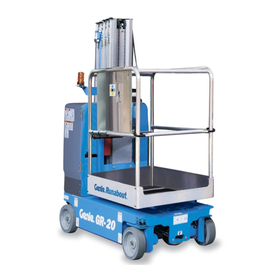
Service Manual
GR
-12
™
GR
-15
™
GR
-20
™
QS
-12R
™
QS
-15R
™
QS
-20R
™
QS
-12W
™
QS
-15W
™
QS
-20W
™
Serial Number Range
from GR10-20000
to GR16-40865
from GR16P-40866
to GR16P-44699
from GRP-44700
from GRR-101
from QS11-1000
to QS16-2429
from QS16P-2430
to QS16P-4499
from QSP-4500
Part No. 1275811GT
Rev A2
May 2018
Advertisement
Table of Contents

Related Manuals for Genie QS-12W


Summarization of Contents
Introduction
Important Information
Safety and operational guidance for maintenance procedures.
Serial Number Legend
Explains the serial number format for models before and after September 1, 2016.
Technical Publications
Information on manual accuracy and suggestions for improvement.
Contact Us
Contact details for Genie support and technical publications.
Safety Rules
Do Not Perform Maintenance Unless
Lists conditions required before performing maintenance on the machine.
Personal Safety
General safety precautions for individuals working on or around the machine.
Workplace Safety
Safety measures related to the work environment and practices.
Specifications
Machine Specifications
Lists physical and electrical specifications for the machine models.
Performance Specifications
Details operational performance metrics like speed and load capacity.
Hydraulic Specifications
Covers hydraulic component, oil, and torque specifications.
Scheduled Maintenance Procedures
Machine Configuration
Specifies the required machine configuration for performing maintenance procedures.
Quarterly Maintenance Procedures
Maintenance tasks to be performed quarterly.
Annual Maintenance Procedures
Maintenance tasks to be performed annually.
Programmed Maintenance Procedures
Maintenance tasks based on machine operating hours.
Repair Procedures
Machine Configuration
Specifies the required machine configuration for performing repair procedures.
Platform Controls
Procedures for repairing platform control components.
Ground Controls
Procedures for repairing ground control components.
Hydraulic Pump
Procedures for repairing the hydraulic pump.
Function Manifold
Procedures for repairing the function manifold.
Mast Components
Procedures for repairing mast-related components.
Obstruction Sensing System
Procedures for obstruction sensing system components.
Batteries
Procedures for removing the machine's batteries.
Diagnostics
Definitions
Defines key terms and acronyms used in the diagnostics section.
GCON I/O Maps
Input/Output maps for Ground Controls and ECM connector layout.
Operational Indicator Codes (OIC)
Explains operational codes displayed on the machine.
Diagnostic Trouble Codes (DTC)
Explains diagnostic trouble codes for system malfunctions.
Troubleshooting Fault Types
Guide to troubleshooting common fault types (HXXX, PXXX, UXXX, FXXX, CXXX).
Battery Charger Diagnostics
Explains charger fault and error codes for diagnosing malfunctions.
Schematics
Electrical Component and Wire Color Legends
Explains electrical components and wire color coding.
Wiring Diagram Ground and Platform Controls
Wiring diagram for ground and platform controls.
Electrical Symbol Legend
Explains electrical symbols used in schematics.
Hydraulic Symbols Legend
Explains hydraulic symbols used in schematics.
Electrical Schematics
Contains electrical schematics for various models and serial number ranges.
Hydraulic Schematics
Contains hydraulic schematics for various models and serial number ranges.
Need help?
Do you have a question about the QS-12W and is the answer not in the manual?
Questions and answers