Table of Contents
Advertisement
Service Manual
The service information is designed for experienced repair technicians only and is not designed for use by the general
public. It does not contain warnings or cautions to advise non-technical individuals of potential dangers in attempting
to service a product. Products powered by electricity should be serviced or repaired only by experienced professional
technicians. Any attempt to service or repair the product or products dealt within this service information by anyone
else could result in serious injury or death.
There are special components used in this equipment which are important for safety. These parts are marked by
in the Schematic Diagrams, Circuit Board Diagrams, Exploded Views and Replacement Parts List. It is essential that
these critical parts should be replaced with manufacturer's specifi ed parts to prevent shock, fi re or other hazards. Do
not modify the original design without permission of manufacturer.
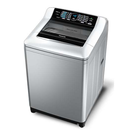
Fully Automatic Washing Machine
WARNING
IMPORTANT SAFETY NOTICE
Order No. PAPTH141101CE
© Panasonic Appliances (Thailand) Co., Ltd. 2014.
All rights reserved. Unauthorized copying and
distribution is a violation of law.
NA-F135X1
NA-F115X1
NA-F135A1
NA-F125A1
NA-F115A1
Product Colour
Stainless Colour (L)
Silver (S)
White (W)
Destination
Thailand, Malaysia
Singapore (Local)
Singapore (Export)
Vietnam
Advertisement
Table of Contents

Related Manuals for Panasonic NA-F125A1


Summarization of Contents
Technical Information
Standard Wash Capacity
Details wash capacity for different courses and models.
Standard Water Supply
Details water supply times for different washing courses.
Installation
Check the location
Instructions for selecting a suitable installation location, avoiding hazards.
Attach the bottom cover
Steps to attach the bottom cover to the washing machine securely.
Attach the external drain water hose
Guidance on connecting the external drain hose correctly, including height limits.
Operation Panel
Change water amount
How to adjust the water level during the wash process.
Water amount/remaining time
Displays the water amount used and the estimated time remaining.
Change process settings
How to modify wash, rinse, and spin settings for individual processes.
Preset
Setting a delay for the washing cycle to finish at a specific time.
Washing
Set how many hours later to finish operation
Setting a timer for the cycle to end at a future time.
When the Fragrance program is selected
Specific instructions for using the Fragrance wash program.
Maintenance
Setting Child Lock
Function to prevent children from tampering with the machine's operation.
Lint filter
Procedure for cleaning the lint filter after each operation.
Test Mode
Check Procedure A
Test mode for checking buzzer, timer, and auto power off functions.
Check Procedure B
Test mode for checking washing, spinning, and lid switch operations.
Check Procedure C
Test mode for adjusting water amount detection settings.
Check Procedure G
Test mode to display the last recorded error message.
Troubleshooting
Time indication issues
Issues related to time display and operation duration.
Main unit issues
Troubleshooting for main unit failures and power problems.
Wash issues
Problems related to water supply and levels during the wash process.
Rinse/Spin issues
Troubleshooting for rinse/spin process and tub rotation problems.
Table of Errors
U-Error indication
Explains U-error codes and their solutions for draining and lid issues.
H-Error indication
H-Error indication
Explains H-error codes for sensor, motor, and PCB issues.
Wiring Diagram
NA-F135X1, NA-F115X1
Wiring diagram specific to NA-F135X1 and NA-F115X1 models.
NA-F135A1, NA-F125A1, NA-F115A1
Wiring diagram specific to NA-F135A1, NA-F125A1, and NA-F115A1 models.
Disassembly
Controller Unit
Step-by-step guide to disassemble the controller unit.
Panel Face B
Steps to disassemble Panel Face B.
Parts Exploded View and Replacement Parts List
Parts Exploded View : Part A
Exploded view of Part A components for identification.
Need help?
Do you have a question about the NA-F125A1 and is the answer not in the manual?
Questions and answers