Denon AVR-983 Operating Instructions Manual
Denon av surround receiver operating instructions avr-2803, avr-983
Hide thumbs
Also See for AVR-983:
- Service manual (113 pages) ,
- Brochure & specs (2 pages) ,
- Control protocol (13 pages)
Table of Contents
Advertisement
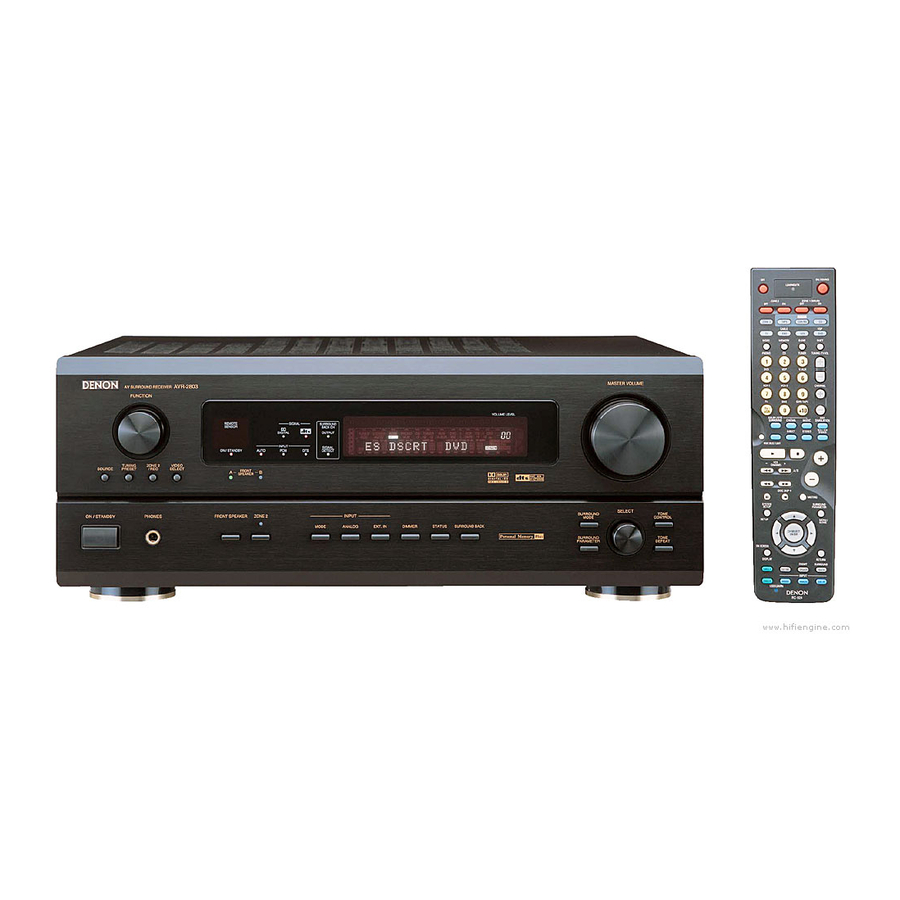
AV SURROUND RECEIVER
AVR-2803/983
OPERATING INSTRUCTIONS
We greatly appreciate your purchase of the AVR-2803/983.
2
To be sure you take maximum advantage of all the features the AVR-2803/983 has to offer, read these
2
instructions carefully and use the set properly. Be sure to keep this manual for future reference, should any
questions or problems arise.
"SERIAL NO.
PLEASE RECORD UNIT SERIAL NUMBER ATTACHED TO THE REAR OF THE
CABINET FOR FUTURE REFERENCE"
REMOTE
SIGNAL
SURROUND
SENSOR
BACK CH
DIGITAL
OUTPUT
INPUT
SIGNAL
ON / STANDBY
AUTO
PCM
DTS
DETECT
VOLUME LEVEL
Advertisement
Table of Contents

Related Manuals for Denon AVR-983


Summary of Contents for Denon AVR-983
-
Page 1: Operating Instructions
AV SURROUND RECEIVER AVR-2803/983 OPERATING INSTRUCTIONS REMOTE SENSOR DIGITAL INPUT ON / STANDBY AUTO We greatly appreciate your purchase of the AVR-2803/983. To be sure you take maximum advantage of all the features the AVR-2803/983 has to offer, read these instructions carefully and use the set properly. -
Page 2: Safety Precautions
SAFETY PRECAUTIONS WARNING: TO PREVENT FIRE OR SHOCK HAZARD, DO NOT EXPOSE THIS APPLIANCE TO RAIN OR MOISTURE. CAUTION RISK OF ELECTRIC SHOCK DO NOT OPEN CAUTION: TO REDUCE THE RISK OF ELECTRIC SHOCK, DO NOT REMOVE COVER (OR BACK). NO USER- SERVICEABLE PARTS INSIDE. -
Page 3: Safety Instructions
SAFETY INSTRUCTIONS Read Instructions – All the safety and operating instructions should be read before the product is operated. Retain Instructions – The safety and operating instructions should be retained for future reference. Heed Warnings – All warnings on the product and in the operating instructions should be adhered to. -
Page 4: Table Of Contents
INTRODUCTION Thank you for choosing the DENON AVR-2803/983 Digital A / V Surround Receiver. This remarkable component has been engineered to provide superb surround sound listening with home theater sources such as DVD, as well as providing outstanding high fidelity reproduction of your favorite music sources. -
Page 5: Cautions On Handling
8. Wide screen mode for a 7.1-channel sound even with 5.1-channel sources DENON has developed a wide screen mode with a new design which recreates the effects of the multi surround speakers in movie theaters. The result is 7.1-channel sound taking full advantage of surround back speakers, even with Dolby Pro Logic or Dolby Digital/DTS 5.1-channel signals. -
Page 6: Connections
5 CONNECTIONS • Do not plug in the AC cord until all connections have been completed. • Be sure to connect the left and right channels properly (left with left, right with right). • Insert the plugs securely. Incomplete connections will result in the generation of noise. -
Page 7: Connecting The Video Components
Connecting the video components • To connect the video signal, connect using a 75 • When making connections, also refer to the operating instructions of the other components. TV or DBS tuner AUDIO VIDEO AUDIO VIDEO Connecting a DVD player or a video disc player (VDP) •... -
Page 8: Connecting Video Component With S-Video Jacks
Connecting the video components equipped with S-Video jacks • When making connections, also refer to the operating instructions of the other components. • A note on the S input jacks The input selectors for the S inputs and Video inputs work in conjunction with each other. •... - Page 9 Connecting the video component equipped with Color Difference (Component - Y, P ) Video jacks • When making connections, also refer to the operating instructions of the other components. • The signals input to the color difference (component) video jacks are not output to the VIDEO output jack (yellow) or the S-Video output jack. •...
-
Page 10: Connecting The Antenna Terminals
Connecting the antenna terminals DIRECTION OF BROADCASTING STATION FM ANTENNA /ohms COAXIAL CABLE FM INDOOR ANTENNA (Supplied) • An F-type FM antenna cable plug can be connected directly. AM loop antenna assembly Connect to the AM antenna terminals. Remove the vinyl tie Bend in the reverse and take out the direction. -
Page 11: Connecting The External Input (Ext. In) Jacks
Connecting the external input (EXT. IN) jacks • These jacks are for inputting multi-channel audio signals from an outboard decoder, or a component with a different type of multi-channel decoder, such as a DVD Audio player, a multi-channel SACD player, or other future multi-channel sound format decoder. •... -
Page 12: Speaker System Connections
Speaker system connections • Connect the speaker terminals with the speakers making sure that like polarities are matched (≈ with ≈ , √ with √ ). Mismatching of polarities will result in weak central sound, unclear orientation of the various instruments, and the sense of direction of the stereo being impaired. - Page 13 If the protection circuit is activated again even though there are no problems with the wiring or the ventilation around the unit, switch off the power and contact a DENON service center. • The protector circuit may be activated if the set is played for long periods of time at high volumes when speakers with an impedance lower than the specified impedance (for example speakers with an impedance of lower than 4 connected.
-
Page 14: Front Panel
6 PART NAMES AND FUNCTIONS Front Panel • For details on the functions of these parts, refer to the pages given in parentheses ( ). Power ON/STANDBY switch...(41, 63) Headphones jack (PHONES) ...(45) VIDEO SELECT button ...(45) Front speaker system indicators (FRONT SPEAKER A/B) FRONT SPEAKER button ...(41, 63) ZONE 2 button/indicator...(47, 63) -
Page 15: Remote Control Unit
Remote control unit • For details on the functions of these parts, refer to the pages given in parentheses ( ). LED (indicator) ...(36) ZONE 2 buttons ...(47) Mode selector buttons ...(32~34, 36~41, 47) Input source selector buttons ...(33~35, 42, 47, 53, 61) MODE SELECT button ...(32) System buttons...(32, 34, 35, 38) SYSTEM SETUP/SETUP... -
Page 16: Setting Up The System
7 SETTING UP THE SYSTEM • Once all connections with other AV components have been completed as described in “CONNECTIONS” (see pages 6 to 13), make the various settings described below on the monitor screen using the AVR-2803/983’s on-screen display function. These settings are required to set up the listening room’s AV system centered around the AVR-2803/983. -
Page 17: Before Setting Up The System
System setup Auto Tuner FM stations are received automatically and stored in the memory. Presets Set whether or not to lock the system setup settings so that they Setup Lock cannot be changed. NOTES: • The on-screen display signals are output with priority to the S-VIDEO MONITOR OUT jack during playback of a video component. For example, if the TV monitor is connected to both the AVR-2803/983’s S-Video and video monitor output jacks and signals are input to the AVR-2803/983 from a video source (VDP, etc.) connected to both the S-Video and video input jacks, the on-screen display signals are output with priority to the S-Video monitor output. -
Page 18: Setting The Type Of Speakers
Setting the type of speakers • Set up in function of your speaker systems. Performing this setup optimizes the system. • The composition of the signals output to the different channels and the frequency response are adjusted automatically according to the combination of speakers actually being used. - Page 19 Setting the crossover frequency and low frequency distribution when playing Dolby Digital and DTS signals • Set the crossover frequency and subwoofer mode according to the speaker system being used. Select the “Crossover Frequency” mode. Select the “Subwoofer Mode”. Enter the setting. The System Setup Menu reappears.
-
Page 20: Setting The Delay Time
Setting the Delay Time • Input the distance between the listening position and the different speakers to set the delay time for the surround mode. Preparations: Measure the distances between the listening position and the speakers (L1 to L5 on the diagram at the right). -
Page 21: Setting The Channel Level
Set the distance between the center speaker and listening position. The distance changes in units of 1 foot (0.1 meters) each time the button is pressed. Select the value closest to the measured distance. If “Yes” is selected for “Default”, the settings are automatically reset to the default values. - Page 22 Select the mode. Select “Auto” or “Manual”. • Auto: Adjust the level while listening to the test tones produced automatically from the different speakers. • Manual: Select the speaker from which you want to produce the test tone to adjust the level. Select “Test Tone Start”.
-
Page 23: Setting The Digital In Assignment
When you adjust the channel levels while in the SYSTEM SETUP CHANNEL LEVEL mode, the channel level adjustments made will affect all surround modes. Consider this mode a Master Channel Level adjustment mode. After you have completed the SYSTEM SETUP CHANNEL LEVEL adjustments, you can then activate the individual surround modes and adjust channel levels that will be remembered for each of those modes. -
Page 24: Setting The Dolby Digital Setup
Setting the Video In Assignment • This setting assigns the color difference (component) video input jacks of the AVR-2803/983 for the different input sources. At the System Setup Menu select “Video In Assignment”. Switch to the Video In Assignment screen. Select the component (Y, P q Input source selection Select “NONE”... - Page 25 Enter the setting. The System Setup Menu reappears. Setting the ZONE2 Control [1] Setting the power amplifier assignment Make this setting to switch the power amplifier for the surround back channel to ZONE2. If ZONE2 is selected, the signal that selected at ZONE2 is output at “SURR. BACK/ZONE2 PREOUT” terminals. Select “Surround Back”...
-
Page 26: Setting The Ext. In Subwoofer Level
Select the desired setting. Variable: The level can be adjusted freely using the buttons on the remote control unit. 0 dB, -40 dB: The output level is fixed at the set level and the volume can no longer be adjusted. Enter the setting. -
Page 27: Setting The Auto Surround Mode
Setting the Auto Surround Mode The surround mode used at last for the three types of input signals shown below is stored in the memory, and the signal is automatically played with that surround mode the next time it is input. Note that the surround mode setting is also stored separately for the different input sources. -
Page 28: Setting The Trigger Out Setup
Setting the Trigger Out Setup • Sets the Trigger Out output for the different input sources. At the System Setup Menu select “Trigger Out Setup”. Switch to the Trigger Out Setup screen. Enter the setting. The System Setup Menu reappears. Auto Tuner Presets Use this to automatically search for FM broadcasts and store up to 40 stations at preset channels A1 to 8, B1 to 8, C1 to 8, D1 to 8 and E1 to 8. - Page 29 Use the CURSOR button to select “Yes”. “Search” flashes on the screen and searching begins. “Completed” appears once searching is completed. The display automatically switches to screen. Protecting the setting The system setup settings can be locked so that they cannot be changed easily. At the System Setup Menu select “Setup Lock”.
-
Page 30: After Completing System Setup
After completing system setup This button can be pressed at any time during the system setup process to complete the process. At the System Setup Menu, press the SYSTEM SETUP button. The changed settings are entered and the on-screen display turns off. •... -
Page 31: Inserting The Batteries
• The included remote control unit (RC-924) can be used to operate not only the AVR-2803/983 but other remote control compatible DENON components as well. In addition, the memory contains the control signals for other remote control units, so it can be used to operate non-Denon remote control compatible products. -
Page 32: Operating Denon Audio Components
Operating DENON audio components Use the mode selector buttons to select the component you want to operate. The function will change one step in the sequence described below each time the MODE SELECT button is pressed. CDR/MD ZONE2 DBS/CABLE Operate the audio component. -
Page 33: Preset Memory
• The preset memory can be set for one component only among the following: CDR/MD, DVD/VDP and DBS/CABLE. The preset codes are as follows upon shipment from the factory and after resetting: TV, VCR ...HITACHI CD, TAPE ...DENON CDR/MD...DENON (CDR) DVD/VDP...DENON (DVD) DBS/CABLE ...ABC (CABLE) -
Page 34: Operating A Component Stored In The Preset Memory
Operating a component stored in the preset memory Press the mode selector button for the component you want to operate. NOTE: • For the DVD player remote control buttons, function names may differ according to manufacturer. control operation of the various components. Operate the component. - Page 35 Channel +, – : Channels NOTES: • For this CD, CDR, MD and TAPE components, buttons can be operated in the same way as for Denon audio components. • The television can be operated in the DVD/VDP, VCR and TV modes.
-
Page 36: Learning Function
Learning function If your AV component is not a Denon product or if it cannot be operated using the preset memory, it can be controlled with the accessorious remote control unit by storing its remote control signals in the remote control unit. -
Page 37: System Call
System call The accessorious remote control unit is equipped with “system call” function allowing a series of remote control signals to be transmitted by pressing a single button. This function can be used for example to turn on the amplifier’s power, select the input source, turn on the monitor TV’s power, turn on the source component’s power and set the source to the play mode, all at a signal button. -
Page 38: Punch Through
(3) Using the system call function Press the button at which the system call signals have been stored. • The stored signals are transmitted successively. Punch Through (1) Punch through button Buttons used in the CD, CDR/MD, TAPE, DVD/VDP, and VCR modes can be assigned to the buttons shown on the diagram at the right which are not normally used in the TV and DBS/CABLE modes. - Page 39 Resetting (1) Resetting “learned” buttons Press the USE/LEARN button with the tip of a pen, etc., to set the learn mode. • The mode selector buttons and LEARNED/TX indicator flash. Flashes Press the mode button of the equipment that is to be reset. •...
- Page 40 (2) Resetting the punch through setting Press the power ON/SOURCE button and the OFF button at the same time. • The LEARNED/TX indicator flashes. Press the 1 (play) button. • TV and DBS/CABLE mode buttons and TEARNED/TX indicator flash. Press the mode button of the equipment (TV or DBS/CABLE) that is to be reset.
-
Page 41: Before Operating
9 OPERATION Before operating Refer to “CONNECTIONS” (pages 6 to 13) and check that all connections are correct. Select “AMP mode” using the TAPE, CDR/MR or CD button. (only when operating with the remote control unit) (Remote control unit) Turn on the power. Press the POWER switch (button). -
Page 42: Playing The Input Source
Playing the input source Select the input source to be played. Example: CD FUNCTION (Main unit) To select the input source when ZONE2/REC OUT or TUNING PRESET is selected, press the SOURCE button then operate the input function selector. Select the input mode. •... - Page 43 Select the play mode. Example: Stereo SELECT (Main unit) To select the surround mode while adjusting the surround parameters, channel volume or tone control, press the surround mode button then operate the selector. (Main unit) Start playback on the selected component. •...
-
Page 44: Playing Audio Sources (Cds And Dvds)
Playback using the external input (EXT. IN) jacks Set the external input (EXT. IN) mode. Press the EXT. IN to switch the external input. Once this is selected, the input signals connected to the FL (front left), FR (front right), C (center), SL (surround left), SR (surround right), SBL (surround back left) and SBR (surround back right) channels of the EXT. - Page 45 After starting playback [1] Adjusting the sound quality (TONE) • The tone control function will not work in the direct mode. • The tone control setting only affects the front speakers. • If the tone control function is used, the main volume cannot be adjusted up to 18 dB. (The maximum main volume level differs in the different surround modes.) The tone switches as follows each time the TONE CONTROL button is pressed.
-
Page 46: Multi-Source Recording/Playback
[5] Checking the currently playing program source, etc. On screen display • Each time an operation is performed, a description of that operation appears on the display connected to the unit’s VIDEO MONITOR OUT jack. Also, the unit’s operating status can be checked during playback by pressing the remote control unit’s ON SCREEN/DISPLAY button. - Page 47 [2] Outputting a program source to an amplifier, etc., in a different room (ZONE2 mode) Press the ZONE2 button. Press the ZONE2/REC button. The display switches as follows each time the button is pressed. With “ZONE2 SOURCE” displayed, turn the FUNCTION knob and select the source you wish to output.
-
Page 48: Multi-Zone Playback With Multi-Source
Back Speaker Out cannot be used for MAIN ZONE. (See page 25.) • When a sold separately room-to-room remote control unit (DENON RC-616, 617 or 618) is wired and connected between the MAIN ZONE and ZONE 2, the remote-controllable devices in the main zone can be controlled from ZONE 2 using the remote control unit. -
Page 49: Surround
10 SURROUND Before playing with the surround function • Before playing with the surround function, be sure to use the test tones to adjust the playback level from the different speakers. This adjustment can be performed with the system setup (see page 21) or from the remote control unit, as described below. •... -
Page 50: Fader Function
Fader function • This function makes it possible to lower the volume of the front channels (FL, C and FR) or the rear channels (SL, SR, SBL and SBR) together. Use it for example to adjust the balance of the sound from the different positions when playing multi-channel music sources. Select “FADER”. - Page 51 Set the surround parameter mode. (Main unit) The on-screen display differs according to whether the operation is performed from the main unit or the remote control unit. Select the play mode. SELECT (Main unit) Display MODE cinema MODE music Select the various parameters. (See “Surround parameters q” for a description of the various parameters.) (Main unit) MODE CINEMA MODE MUSIC...
-
Page 52: Dts Neo:6 Mode
DTS NEO:6 mode • Surround playback can be performed for the analog input and PCM digital input 2-channel signals. Select the DTS NEO:6 mode. SELECT (Main unit) Play a program source. Set the surround parameter mode. (Main unit) This is the screen when operated with the remote control unit. - Page 53 Dolby Digital mode (only with digital input) and DTS Surround mode (only with digital input) Select the input source. Playback with a digital input q Select an input source set to digital (COAXIAL/OPTICAL) (see page 23). FUNCTION (Main unit) w Set the input mode to “AUTO” or “DTS”. (Main unit) Select the Dolby/DTS Surround mode.
- Page 54 (Main unit) (Remote control unit) NOTE: The display on the screen differs depending on whether you are performing the operation from the main unit or the remote control unit. Select the various parameters. (Main unit) (Remote control unit) Dialogue Normalization The dialogue normalization function is activated automatically when playing Dolby Digital program sources.
-
Page 55: Surround Modes And Their Features
11 DSP SURROUND SIMULATION • The AVR-2803/983 is equipped with a high performance DSP (Digital Signal Processor) which uses digital signal processing to synthetically recreate the sound field. One of seven preset surround modes can be selected according to the program source and the parameters can be adjusted according to the conditions in the listening room to achieve a more realistic, powerful sound. - Page 56 DSP surround simulation • To operate the surround mode and surround parameters from the remote control unit. Select the surround mode for the input channel. (Remote control unit) The surround mode switches in the following order each time the DSP SIMULATION button is pressed: MONO MOVIE VIRTUAL...
- Page 57 • Operating the surround mode and surround parameters from the main unit‘s panel. Turn the SELECT knob to select the surround mode. SELECT (Main unit) • When turned clockwise DIRECT STEREO DOLBY PRO LOGIC VIRTUAL MATRIX • When turned counterclockwise DIRECT STEREO DOLBY PRO LOGIC...
-
Page 58: Tone Control Setting
Tone control setting • Use the tone control setting to adjust the bass and treble as desired. • To operate the tone control from the remote control unit. • The tone control setting only affects the front speakers. • If the tone control function is used, the main volume cannot be adjusted up to 18 dB. (The maximum main volume level differs in the different surround modes.) Display the surround parameter screen on the monitor. -
Page 59: Mode: (Dts Neo:6)
• To operate the tone control from the main unit. The tone switches as follows each time the TONE CONTROL button is pressed. BASS (Main unit) With the name of the volume to be adjusted selected, turn the SELECT knob to adjust the level. SELECT •... - Page 60 Surround modes and parameters Channel output Mode FRONT L/R CENTER DIRECT STEREO EXTERNAL INPUT DOLBY PRO LOGIC DTS NEO:6 DOLBY DIGITAL DTS SURROUND (DTS ES MTRX 6.1) 5/7CH STEREO ROCK ARENA JAZZ CLUB VIDEO GAME MONO MOVIE MATRIX VIRTUAL C : Signal No signal B : Turned on or off by speaker configuration setting SURROUND PARAMETER...
-
Page 61: Manual Tuning
12 LISTENING TO THE RADIO • Check that the remote control unit is set to AMP mode (TAPE, CDR/MD or CD). Auto tuning Set the input function to “TUNER”. FUNCTION (Main unit) Watching the display, press the BAND button to select the desired band (AM or FM). -
Page 62: Checking The Preset Stations
Preset memory Use the “Auto tuning” or “Manual tuning” operation to tune in the station to be preset in the memory. Press the MEMORY button. (Remote control unit) Press the SHIFT button and select the desired memory block (A to E). (Remote control unit) Press the CHANNEL + (up) or –... -
Page 63: Recalling Preset Stations
Recalling preset stations • Recalling preset stations from the remote control unit. Watching the display, press the SHIFT button to select the preset memory block. (Remote control unit) Watching the display, press the CHANNEL + (up) or – (down) button to select the desired preset channel. -
Page 64: Troubleshooting
15 TROUBLESHOOTING If a problem should arise,first check the following table. 1. Are the connections correct ? 2. Have you operated the receiver according to the Operating Instructions ? 3. Are the speakers, turntable and other components operating property ? If this unit is not operating properly, check the items listed in the table below. -
Page 65: Additional Information
16 ADDITIONAL INFORMATION Optimum surround sound for different sources There are currently various types of multi-channel signals (signals or formats with more than two channels). Types of multi-channel signals Dolby Digital, Dolby Pro Logic, DTS, high definition 3-1 signals (Japan MUSE Hi-Vision audio), DVD-Audio, SACD (Super Audio CD), MPEG multi- channel audio, etc. -
Page 66: Surround Back Speakers
SCREEN mode is a mode for achieving surround sound with up to 7.1 channels using surround back speakers, for sources recorded in conventional Dolby Surround as well as Dolby Digital 5.1-channel and DTS Surround 5.1-channel sources. Furthermore, all the Denon original surround modes (see page 55) are compatible with 7.1-channel playback, so you can enjoy 7.1-channel sound with any signal source. -
Page 67: Speaker Setting Examples
Speaker setting examples Here we describe a number of speaker settings for different purposes. Use these examples as guides to set up your system according to the type of speakers used and the main usage purpose. 1. DTS-ES compatible system (using surround back speakers) (1) Basic setting for primarily watching movies •... - Page 68 Surround The AVR-2803/983 is equipped with a digital signal processing circuit that lets you play program sources in the surround mode to achieve the same sense of presence as in a movie theater. Dolby Surround (1) Dolby Digital Dolby Digital is the multi-channel digital signal format developed by Dolby Laboratories. Dolby Digital consists of up to “5.1”...
-
Page 69: Dts Digital Surround
3 A DVD player with DTS-compatible digital output is required to play DTS DVDs. A DTS Digital Output logo is featured on the front panel of compatible DVD players. Recent DENON DVD player models feature DTS-compatible digital output – consult the player’s owner’s manual for information on configuring the digital output for DTS playback of DTS-encoded DVDs. -
Page 70: Dts-Es Extended Surround
DTS-ES Extended Surround DTS-ES Extended Surround is a new multi-channel digital signal format developed by Digital Theater Systems Inc. While offering high compatibility with the conventional DTS Digital Surround format, DTS-ES Extended Surround greatly improves the 360-degree surround impression and space expression thanks to further expanded surround signals. - Page 71 DTS 96/24 The sampling frequency, number of bits and number of channels used for recording of music, etc., in studios has been increasing in recent years, and there are a growing number of high quality signal sources, including 96 kHz/24 bit 5.1-channel sources. For example, there are high picture/sound quality DVD video sources with 96 kHz/24 bit stereo PCM audio tracks.
- Page 72 System setup items and default values (set upon shipment from the factory) System setup Input the combination of speakers in your system and their Speaker corresponding sizes (Small for regular speakers, Large for full-size, Configuration full-range) to automatically set the composition of the signals output from the speakers and the frequency response.
-
Page 73: Surround Modes And Parameters
Surround modes and parameters Channel output SURROUND Mode FRONT L/R CENTER DIRECT STEREO EXTERNAL INPUT DOLBY PRO LOGIC DTS NEO:6 DOLBY DIGITAL DTS SURROUND (DTS ES MTRX 6.1) 5/7CH STEREO ROCK ARENA JAZZ CLUB VIDEO GAME MONO MOVIE MATRIX VIRTUAL C : Signal No signal B : Turned on or off by speaker configuration setting... - Page 74 Differences in surround mode names depending on the input signals Surround Mode ANALOG LINEAR PCM DIRECT STEREO DTS SURROUND DTS NEO:6 DTS NEO:6 DOLBY SURROUND DOLBY PRO LOGIC PRO LOGIC DSP SIMULATION C : Selectable : The surround mode name differs depending on the “SB CH OUT” surround parameter setting. B : The surround mode name differs depending on the input signal.
-
Page 75: Specifications
17 SPECIFICATIONS Audio section • Power amplifier Rated output: Dynamic power: Output terminals: • Analog Input sensitivity / input impedance: Frequency response: S/N: Distortion: Rated output: • Digital D/A output: Digital input: • Phono equalizer (PHONO input — REC OUT) Input sensitivity: RIAA deviation: Signal-to-noise ratio:... - Page 76 16-11, YUSHIMA 3-CHOME, BUNKYOU-KU, TOKYO 113-0034, JAPAN Telephone: (03) 3837-5321 Printed in Japan 511 4012 002...
Need help?
Do you have a question about the AVR-983 and is the answer not in the manual?
Questions and answers