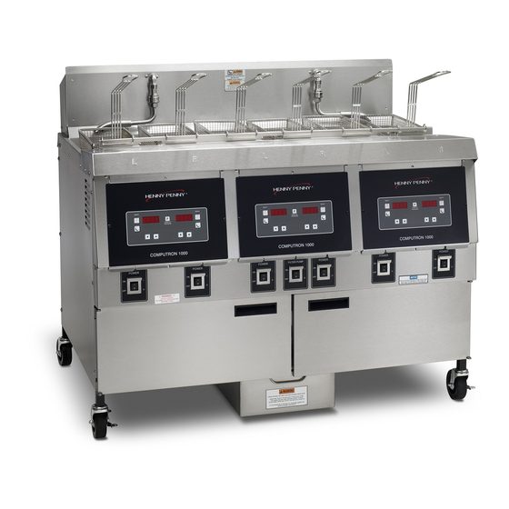
Summarization of Contents
SECTION 1. TROUBLESHOOTING
1-1. INTRODUCTION
Provides troubleshooting information in an easy-to-read table.
1-3. TROUBLESHOOTING
Instructions for isolating a malfunction using a troubleshooting table.
1-4. ERROR CODES
Details error messages, their causes, and correction procedures.
SECTION 2. MAINTENANCE
2-1. INTRODUCTION
Procedures for checkout and replacement of fryer parts.
2-3 HIGH TEMPERATURE LIMIT CONTROL (Gas Units)
Details the high temperature limit control for gas units.
2-6. TEMPERATURE PROBE REPLACEMENT
Steps for replacing the temperature probe if it fails or is out of calibration.
2-16. GAS CONTROL VALVE ASSEMBLY
Procedure for removing and replacing the gas control valve assembly.
2-18. HEATING ELEMENTS (ELECTRIC ONLY)
Procedure for checking and replacing heating elements in electric units.
2-21. HIGH TEMPERATURE LIMIT CONTROL (Electric Units)
Procedure for replacing the high temp limit control on electric models.
WIRING DIAGRAMS
120 Volt
Wiring diagram for 120 Volt models.
208/240 Volt (Domestic)
Wiring diagram for 208/240 Volt domestic models.
Computron 1000 Wiring Diagrams
Wiring diagrams for Computron 1000 systems.
LIMITED WARRANTY FOR HENNY PENNY EQUIPMENT
NEW EQUIPMENT
Warranty terms for new appliances, excluding baskets, lamps, and fuses.
EXTENDED FRYPOT WARRANTY
Warranty for frypots against manufacturing issues for up to seven years.
SECTION 3. PARTS INFORMATION
3-1. INTRODUCTION
Lists replaceable parts for OFE/OFG-32x Open Fryers.
3-3. WHEN ORDERING PARTS
Information required when ordering replacement parts.
3-3. GAS HEAT
Lists replaceable parts for the gas heat system.
3-4. Electric Heat Controls
Diagram illustrating electric heat control components.
3-18. GAS VALVE ASSEMBLIES
Diagrams and parts list for gas valve assemblies.
3-24. Electric Heater
Diagram and parts list for electric heater components.


Need help?
Do you have a question about the OGA-322 and is the answer not in the manual?
Questions and answers