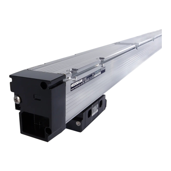
Summarization of Contents
Mounting Procedure
Mounting Location Selection
Select mounting location to prevent scanning unit from hitting housing covers.
Vertical Mounting - Drain Screw
For vertical mounting without compressed air, remove the drain screw.
Sealing Lips Protection
Position the unit with sealing lips away from contamination sources.
Preparatory Work
Loosen Shipping Braces
Loosen the screws on the shipping braces of the scanning unit slightly.
Remove Brace Clip
Remove the shipping brace clip.
Attach Adapter Cables
Attach adapter cables (1 Nm) ensuring the bending radius meets specifications.
Changing the Cable Outlet
ESD Protection
Protect electronics from static discharge by using a grounded bracelet.
Detach Cover and Cables
Unscrew the cover and any adapter cables.
PCB Handling
Tilt, pull out, and rotate the PCB 180°. Insert connector first, avoid pinching wires.
Re-attach Cover and Cables
Re-attach the cover and adapter cables with screws (1 Nm).
Reference Mark Position LB 302/LB 382
Activation Intervals
Reference marks can be activated at mounting holes and 50 mm intervals.
Default Activation
By default, the reference mark is active at the midpoint of the measuring length.
Indicate Position
Mark the desired reference mark position on the housing with the RM label.
Set Position
Insert the reference mark slider through sealing lips and position the selector plate.
Dimensions, Standard Version
Tolerancing Standards
Specifies tolerances according to ISO 8015 and ISO 2768 for dimensions under 6 mm.
Dimensions, Mirror-Imaged Version
Tolerancing Standards
Specifies tolerances according to ISO 8015 and ISO 2768 for dimensions under 6 mm.
Mounting Tolerances
Mounting Possibilities and Tolerances
Shows mounting possibilities and associated tolerances.
Horizontal Mounting Attitude
Indicates that horizontal mounting is a possible installation orientation.
Mounting
Surface Preparation
Prepare mounting surface by drilling holes and ensuring it is paint-free.
Secure Encoder Loosely
Secure the encoder by initially attaching screws loosely.
Cover Mounting Option
Mounting option on the scanning unit cover. Attach screws loosely.
Remove Shipping Braces
Slide shipping braces sideways and remove them from the scanning unit.
Checking the Encoder
Parallelism Check
Check parallelism to machine guideway F at ends and other positions.
Gap Setting and Tightening
Set scanning gap using gauge and tighten screws to specified torque.
Final Steps
Shielding Resistance Check
Measure resistance between connector housing and scale unit; max 1 Ω.
Tolerance and Function Check
Verify mounting tolerances and encoder function across the full traverse range.
Linear Error Compensation
Compensation Method
Linear error compensation up to ±100 µm/m can be applied via the tape tensioning device.
Measurement Setup
Set up a comparator system (e.g., laser interferometer) and measure the machine.
Remove Plug PF
Remove the PF plug.
Calculate Compensation Value
Calculate compensation value K by measuring distance XK and using LK from machine measurement.
Tensioning the Scale Tape
Set Tape Tension
Tension the scale tape to the previously calculated value.
Replace Plug PF
Re-insert the PF plug after tensioning.
Protective Measures
Additional Cover
For high contamination risk, use an additional cover with a seal.
Compressed Air Usage
Use compressed air via connecting piece, ensuring it is clean and dry.
Compressed Air Connection (Scanning Unit)
Connect compressed air to the scanning unit; unit is an accessory.
Compressed Air Connection (Scale Ends)
Connect compressed air at the scale end sections.
Electrical Connection LB 302/LB 302 C
9-pin HEIDENHAIN Connector
Details of the 9-pin HEIDENHAIN connector pinout.
9-pin D-Sub Connector
Details of the 9-pin D-Sub connector pinout.
Electrical Data LB 302/LB 302 C
Power Supply and Output Signals
Specifies power supply voltage and output signal characteristics.
Incremental Signals
Details incremental signal amplitude under 1 kΩ load.
Reference Mark Signals
Details reference mark signal amplitude under 1 kΩ load.
Cable Length
Maximum permissible cable length to subsequent electronics.
Electrical Connection LB 382/LB 382 C
12-pin HEIDENHAIN Connector
Details of the 12-pin HEIDENHAIN connector pinout.
12-pin HEIDENHAIN Coupling
Details of the 12-pin HEIDENHAIN coupling pinout.
Electrical Data LB 382/LB 382 C
Power Supply and Output Signals
Specifies power supply voltage and output signal characteristics.
Incremental Signals
Details incremental signal amplitude with terminating resistor.
Reference Mark Signals
Details reference mark signal amplitude with terminating resistor.
Cable Length
Maximum permissible cable length to subsequent electronics.
Mechanical Data
Measuring Standard and Reference Marks
Details the measuring standard, grating period, thermal expansion, and reference mark selection.
Performance Specifications
Covers max speed, acceleration limits (vibration, shock), and required moving force.
Environmental and Connection Specs
Includes protection type, operating/storage temperatures, and cable bending radii.


Need help?
Do you have a question about the LB 382 C and is the answer not in the manual?
Questions and answers