
Related Manuals for PROVA 19


Summary of Contents for PROVA 19
- Page 1 Power Harmonics and Leakage Tester Model 21/23 Leakage and Harmonics Tester Model 19 Users Manual PROVA INSTRUMENTS INC.
- Page 2 EN 61010-2-032 CAT II 600V CAT III 300V Pollution Degree 2 Definition of Symbols: Caution: Refer to Accompanying Documents Caution: Risk of Electric Shock Double Insulation Over-voltage Category I (CAT I): Equipment for connection to circuits in which measures are taken to limit the transient over-voltages to an appropriate low level.
-
Page 3: Table Of Contents
III.3.4. Horse Power (H.P.)....................19 III.3.5. Energy (mWH, WH, or KWH)................19 III.4 Measurement of the Balanced 3 Phase AC Power Quality (21, 23)....20 III.5 Measurement of the Balanced 3 Phase Sequence (21, 23)......21 IV. SET THE CT RATIO ....................22 V. -
Page 4: Features
Programmable CT ratio from 1 to 250. l. Max, Min and data hold functions. m. Leakage current measurement at 10μA resolution. n. Active power in H.P. o. Auto power off function in 30 minutes. p. Shielded Jaw immune to external interference (Model 19, 21) -
Page 5: Panel Description
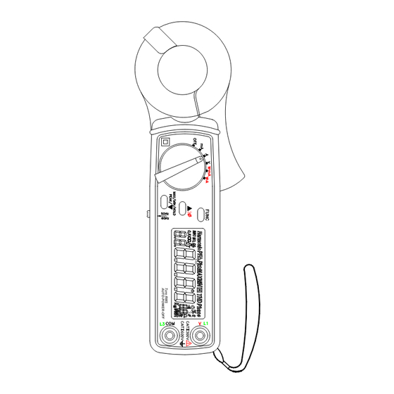
II. PANEL DESCRIPTION Ture RMS AUTO-POWER-OFF 1. Transformer Jaw Assembly This is used to pick up current signal. To measure AC current or Power/Watt, the jaw must enclose conductor completely. 2. Transformer Trigger Press the trigger to open the jaw. 3. - Page 6 5. ▲ 3Φ Button This button is used to increment order of harmonics or CT ratio. When the rotary switch is set at W-mA or W-A position, press this button to select measurement of balanced 3Φ power instead of single-phase power. This button is also used to select AUTO Hz.
- Page 7 18. Sliding Switch Users should select the correct fundamental frequency (50/60 Hz) by moving the sliding switch to a correct position.
-
Page 8: Operating Instructions
III. OPERATING INSTRUCTIONS III.1. Measurement of AC mA and A NOTE: 1. Select the correct fundamental frequency (50 or 60 Hz) of current by moving the sliding switch at the side of the tester. Or hold the ▲ button to select AUTO Hz. 2. -
Page 9: Iii.1.1. True Rms Value Of Ac Current
WARNING: Make sure that all the test leads are disconnected from the meter's terminals for current measurement. III.1.1. True RMS value of AC Current... -
Page 10: Iii.1.2. Hold, Max, Min And Peak Of Ac Current
a. Set the rotary switch at mA or A depending on the range of AC current. Then select the correct frequency by moving the sliding switch at the side of the tester. b. Press the trigger to open the jaw and fully enclose the conductor to be measured. -
Page 11: Iii.1.3. Harmonics Of Ac Current In Magnitude (Ma Or A)
III.1.3. Harmonics of AC Current in Magnitude (mA or A) a. Set the rotary switch at the position of “mA” or “A” depending on the range of AC current. Then select the correct fundamental frequency by moving the sliding switch at the side of the tester. b. -
Page 12: Iii.1.5. Total Harmonic Distortion (% Thd-F)
measured. Press the FUNC button twice. The symbols of “Harmonic” and “NO” will be shown in LCD. The n-th order (1 to 99) will be shown in front of the reading of the percentage (%) of the current. d. Press the ▲ or ▼ button to increment or decrement the order of harmonics in front of the reading. -
Page 13: Iii.1.6. Crest Factor (C.f.)
III.1.6. Crest Factor (C.F.) a. Set the rotary switch at the position of “mA” or “A” depending on the range of AC current. Then select the right frequency by moving the sliding switch at the side of the tester. b. Press the trigger to open the jaw and fully enclose the conductor to be measured. -
Page 14: Iii.2 Measurement Of Ac Voltage
III.2 Measurement of AC Voltage NOTE: 1. Select the correct fundamental frequency of voltage by moving the sliding switch at the side of the tester. 2. If the peak value of the input AC voltage is greater than the maximum value of the range, then symbol of OL will be displayed. -
Page 15: Iii.2.1. True Rms Value Of Ac Voltage
III.2.1. True RMS value of AC Voltage a. Set the rotary switch at position V. Then select the correct fundamental frequency by moving the sliding switch at the side of the tester. b. Insert the test leads into the input jack. Connect the test prods of the test leads in PARALLEL to the circuit to be measured. -
Page 16: Iii.2.3. Harmonics Of Ac Voltage In Magnitude (V)
III.2.3. Harmonics of AC Voltage in Magnitude (V) a. Set the rotary switch at position V. Then select the correct fundamental frequency by moving the sliding switch at the side of the tester. b. Insert the test leads into the input jack. Connect the test prods of the test leads in PARALLEL to the circuit to be measured. -
Page 17: Iii.2.5. Total Harmonic Distortion (% Thd-F)
III.2.5. Total Harmonic Distortion (% THD-F) a. Set the rotary switch at position V. Then select the correct fundamental frequency by moving the sliding switch at the side of the tester. b. Insert the test leads into the input jack. Connect the test prods of the test leads in PARALLEL to the circuit to be measured. -
Page 18: Iii.2.6. Crest Factor (C.f.)
III.2.6. Crest Factor (C.F.) a. Set the rotary switch at position V. Then select the correct fundamental frequency by moving the sliding switch at the side of the tester. b. Insert the test leads into the input jack. Connect the test prods of the test leads in PARALLEL with the circuit to be measured. -
Page 19: Iii.3 Measurement Of Single Phase Ac Power Quality (21, 23)
III.3 Measurement of Single Phase AC Power Quality (21, 23) NOTE: 1. Select the correct fundamental frequency of current and voltage by moving the sliding switch at the side of the tester. 2. Select the proper position of the rotary switch for the range of current. If the AC current is less than 0.6A, then set the rotary switch at the position of W-mA. -
Page 20: Iii.3.1 Single Phase Ac Watt
III.3.1 Single Phase AC Watt a. Connect the test leads to the voltage source in parallel with the load. b. Clamp on one of the wire to the load. The current should flow from the front of the tester to the side of the battery cover. c. -
Page 21: Iii.3.3. Power Factor (Pf), And Phase Angle (Φ)
III.3.3. Power Factor (PF), and Phase Angle (Φ) a. Connect the test leads to the voltage source in parallel with the load. b. Clamp on one of the wire to the load. The current should flow from the front of the tester to the side of the battery cover. -
Page 22: Iii.3.4. Horse Power (H.p.)
III.3.4. Horse Power (H.P.) a. Connect the test leads to the voltage source in parallel with the load. b. Clamp on one of the wire to the load. The current should flow from the front of the tester to the side of the battery cover. c. -
Page 23: Iii.4 Measurement Of The Balanced 3 Phase Ac Power Quality (21, 23)
III.4 Measurement of the Balanced 3 Phase AC Power Quality (21, 23) a. Connect the black test lead to the voltage L3, and connect the red test lead to b. Clamp on one of the wire to L2. The current should flow from the front of the tester to the side of the battery cover. -
Page 24: Iii.5 Measurement Of The Balanced 3 Phase Sequence (21, 23)
III.5 Measurement of the Balanced 3 Phase Sequence (21, 23) a. Hold the ▼ button, and then turn the power on. Set the rotary switch at the W-mA or W-A position. b. Connect the black test lead to the voltage L3, and connect the red test lead to... -
Page 25: Set The Ct Ratio
c. Clamp on to the wire of L2. The current should flow from the front of the tester to the side of the battery cover. d. Press the ▲ button to select 3 phase power system. A symbol of 3Φ will be shown in LCD. -
Page 26: Specifications (23°C±5°C)
AC Watt (50 or 60 Hz, PF 0.6 to 1. CT = 1, Voltage is greater than AC 4V, Current is greater than AC 1mA for mA range, and Current is greater than AC 0.04A for A range. Specification applies to continuous waveforms) Model 21 1, 2 Range (0 to 30A) - Page 27 3, 4 Model 21 Range (30 – 50A) Resolution Accuracy Model 23 Range (60 – 100A) 0.050 – 9.999 W 0.001W ±2% of VA ± 5dgts 10.00 – 99.99 W 0.01W ±2% of VA ± 5dgts 100.0 – 999.9 W 0.1W...
- Page 28 AC Current (Accuracy is of Reading, Auto Range, True RMS, Crest Factor < 4, CT=1, Max. peak values 880mADC for mA range, 73.5ADC for A range, and Overload Protection AC 600A) Model 19,21 5, 6 Range Resolution Accuracy (50/60Hz) 0.5 – 60mA 0.01mA...
- Page 29 1A for A range. AC Voltage (Accuracy is of reading, Auto Range, True RMS, Crest Factor < 4, Input Impedance 10 MΩ, Max peak value 860VDC, and Overload Protection AC 800V) Model 19, 21, 23 Range Resolution Accuracy (50/60Hz) 5V –...
- Page 30 Harmonics of AC Voltage in Magnitude (1 to 99 order, minimum voltage at 50 or 60 Hz is greater than AC 80V) Range (Model 19, 21) Resolution Accuracy 1 – 10 0.1 V ±1% of reading ±7dgts 11 – 20 0.1 V...
- Page 31 A(45 - 65Hz) 0.1Hz ± 0.5Hz 1A to 100A Sensitivity (PROVA 19, 21): > 20mA for mA range, > 1A for A range, and > 50V Sensitivity (PROVA 23): > 20mA for mA range, > 3A for A range, and > 50V...
- Page 32 Peak Value of AC Periodic Voltage (peak value > 10V) or AC Periodic Current (peak value > 10mA for mA range and peak value > 0.5A for A range) for continuous waveform except for square wave: Model 19, 21, 23 Range Sampling Time...
- Page 33 Indoor Use Conductor Size: 30mm (approx.) Battery Type: two 1.5V SUM-3 Display: 4+2+2 digits LCD Range Selection: Auto Overload Indication: Power Consumption: 10mA (approx.) Low battery Indication: Auto-Power-Off: 30 minutes after power-on Update Time: 2 times/sec. (display) No. Of Samples per Period 512 (voltage or current) 256 (power) Temperature Coefficient...
-
Page 34: Battery Replacement
VII. BATTERY REPLACEMENT When the low battery symbol is displayed on the LCD, replace the old batteries with two new batteries. A. MUST Turn the power off and remove the test leads from the clamp meter. B. Remove the screw of the battery compartment. C. -
Page 35: Maintenance & Cleaning
VIII. MAINTENANCE & CLEANING Servicing not covered in this manual should only be performed by qualified personnel. Repairs should only be performed by qualified personnel. Periodically wipe the case with a damp cloth and detergent; do not use abrasives or solvents.
Need help?
Do you have a question about the 19 and is the answer not in the manual?
Questions and answers