Table of Contents
Advertisement
Quick Links
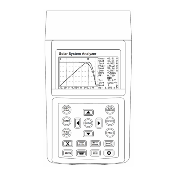
PROVA 1011
Solar System Analyzer
Users Manual
PROVA INSTRUMENTS INC.
This unit (excluding Remote Solar Detector 1012) passes
the following tests:
EN 61010-1: 2010
EN 61010-2-030: 2010
CAT II 1000V, CAT III 300V
Pollution Degree 2
EN61326-1: 2006 Class B
(CISPR 11: 2009/A1: 2010 Group 1 Class B,
EN 61326-1: 2006, IEC 61000-4-2: 2008,
IEC 61000-4-3: 2006+A1:2007+A2:2010,
IEC 61000-4-8: 2009)
Safety Symbols
Please read the statement thoroughly to prevent injury or
loss of life, and prevent damage to this product.
Earth (ground)
DC (Direct Current)
Advertisement
Table of Contents

Related Manuals for PROVA 1011


Summary of Contents for PROVA 1011
- Page 1 This unit (excluding Remote Solar Detector 1012) passes PROVA 1011 the following tests: EN 61010-1: 2010 Solar System Analyzer EN 61010-2-030: 2010 Users Manual CAT II 1000V, CAT III 300V Pollution Degree 2 EN61326-1: 2006 Class B (CISPR 11: 2009/A1: 2010 Group 1 Class B,...
- Page 2 45℃ / 113℉ . Do not dispose of this instrument as unsorted © 2013 PROVA INSTRUMENTS INC. All rights reserved. municipal waste. Contact a qualified recycler for disposal. Caution: 1. The ventilation openings on the unit should not be blocked.
-
Page 3: Table Of Contents
Table of Contents Table of Contents D. Verify the Best Installation Angles of Solar Panels....51 Preparation ....................1 VI. Specifications ..................52 II. Features ....................2 Electrical Specifications ............52 III. Panel Description..................4 General Specifications ............56 Solar system analyzer..............4 VII. Battery Replacement (Recharging) ..........59 Remote Solar Detector 1012 (with Thermometer)....11 VIII. -
Page 4: Preparation
I. Preparation II. Features This Solar system analyzer and the Remote solar detector use rechargeable I-V curve test for solar system ■ lithium batteries. Max. solar system power (Pmax) search by Auto-scan: ■ 1000V, 12A (12000W capability) The rechargeable lithium batteries are pre-installed in the solar system The analyzer and the Remote Solar Detector is connected by Bluetooth ■... -
Page 5: Panel Description
Users can set up the series number of solar panels. Parameters of ■ many solar panels can be measured in one measurement. III. Panel Description The irradiances and temperatures of solar panels can be continuously ■ measured, monitored and recorded. A. - Page 6 Press this button to display or conceal the SOFTWARE KEYBOARD POWER STC POWER button which be used to type in characters. Press this button to switch the display to STC or OPC curves; AUTO AUTO SCAN button SCAN or press it to enter POWER mode. Auto scan I-V curve test.
- Page 7 increment value by 1 or display the file of next page. A-2 REAR PANEL MODULE REF MODULE button Enter/Exit the editing function of solar panel parameters. REPORT REPORT button Press this button to display Standard Test Condition (STC) report and OPerating Condition (OPC) report, or search the Remote Solar Detector again.
- Page 8 3. Terminal for connecting Solar 15 DC Current Probe 4. Stand A-3 TOP PANEL 5. Battery cover 6. Screw of battery cover Note: DO NOT BLOCK VENTILATION OPENINGS When the Analyzer is under POWER mode, the PC Application Software can not communicate with the 1000V MAX 12A MAX Analyzer.
-
Page 9: Remote Solar Detector 1012 (With Thermometer)
Note: Apply Thermal conductive gel on the metal part B. Remote Solar Detector 1012 (with Thermometer) of Auxiliary thermometer, then stick it on solar panel (back side) to detect the temperature of solar panel. Remote Solar Detector (RSD for short) And Thermal conductive gel can be removed easily. -
Page 10: Operation
A. Connecting Diagram IV. Operation Warning: To avoid risk of electric shock and damage to the unit, do not touch any internal components with tools of any kind through the ventilation opening. Warning: AC adaptor is used for lithium battery recharging only. - Page 11 Two Wire Measurement With the “4-wire to 2-wire connecting cable”, users only need 2 testing clips which must touch the metal parts of the output terminals of a solar panel. The “4-wire to 2-wire connecting cable” can convert four wire measurement to two wire measurement.
- Page 12 Four Wire Measurement (with 2 optional testing clips) All 4 testing clips must touch the metal parts of the output terminals of a solar panel. Connect the Solar panel (front side) with Remote solar detector Use Thermal conductive gel to stick Auxiliary thermometer on the Solar panel (back side)
-
Page 13: Auto Scan
Based upon above parameters, Analyzer will scan again to draw two B. AUTO SCAN curves on LCD: the 1 one is I-V curve; the 2 one is P-V curve. 7. Users can Press button to move the cursor along the curve 1. - Page 14 panel parameters. AUTO SCAN of Intelligent Test Logic 3. After turn on the power of Analyzer, if Irr shows ”-----“ then please turn on the Analyzer again to let Irr shows normal values. This Analyzer can perform the AUTO SCAN of intelligent test logic to get a 4.
-
Page 15: Report
C. REPORT 1. After AUTO SCAN finished and curves displayed, or after open a REC REPORT file under FILE LIST, press (REPORT) button to display test report like below: it shows NOMINAL parameters, OPC / STC report. But if Irr shows ”-----“, or Irr ≦ 10 W/m , the report can not be displayed. -
Page 16: File List
D. FILE LIST FILE EXIT 1. Press (FILE EXIT) button to display the File List as below. 2. In the File List you can see: File names, File types, File dates/times. 3. There are four file types: ”Mod” : File of Solar panel parameters. ”REC”... -
Page 17: Ref Module
Beta: Temperature coefficient of solar panel Voc. Gamma: Temperature coefficient of solar panel Pmax. E. REF MODULE K: Temperature coefficient of solar panel Rs. After the parameter tests of OPerating Condition (OPC), the Analyzer can 3. Users can press button or button to select a parameter. -
Page 18: Software Keyboard
F. SOFTWARE KEYBOARD G. ZERO Calibration Users can use SOFTWARE KEYBOARD to type in characters, numbers and Calibration of voltage and current zero would improve the accuracy of the symbols. instrument before usage. 1. Move to the item where you want to change the characters (e.g. First connect “4-wire to 2-wire cable”... -
Page 19: Data Logging
H. Data Logging 4. Under Irr Tc mode, press REC button then the data is recorded once every 60 minutes. Press REC button again to stop Data Logging. Users can perform Data Logging to: record the I-V curves of solar system; Note: or (under POWER mode) record the DC/AC output power, Efficiency;... -
Page 20: Clear Recorded (File) Data And Restore Defaults
Clear Recorded (File) Data and Restore Defaults J. SETUP Parameters Users can clear the recorded data saved in the Analyzer and restore the SETUP 1. Press (SETUP) button to enter the Parameter Setting. factory defaults. 2. Press buttons to select the setting item. The procedures are: 1. -
Page 21: Thermometer Setup
Irr Correction:the factory default of Irr Correction is 0. K. THERMOMETER Setup However, after recalibration if users find there is a measurement deviation on the Irradiance, users can adjust this Irr Correction parameter in order to measure the correct irradiance. Please MODULE 1. -
Page 22: Power Mode
The connection of Solar 21 (AC Power Clamp), Analyzer and Solar 15 (DC L. POWER Mode Current Probe) are as below: Solar System with Panels and Inverter The POWER mode is used to continuously measure/monitor/record the DC power output of solar system and the AC power output of Inverter (1 phase or balanced 3 phases);... - Page 23 Isc: Current at short circuit 1. Turn on the switch of Remote Solar Detector. Pmax: Max. solar system power 2. Press button to turn on the Analyzer. After appr. 3 sec., the Vpm: Max. voltage at Pmax Ipm: Max. current at Pmax Bluetooth connection symbol on the analyzer will change from which means the Bluetooth connection is successful.
- Page 24 EFF(DC-AC): Efficiency, (P(AC)/P(DC))x100 EFF : Average Efficiency, (Ph(AC)/Ph(DC))x100 P : Average Power PF : Average Power Factor Ph: Watt/ hour η 4. Press button to switch the display to DC power curve as below. POWER η Press button again to switch the display to AC power curve as POWER below.
-
Page 25: Irradiance/Temperature (Irr Tc) Mode
Note: M. Irradiance/Temperature (Irr Tc) Mode 1. Under POWER mode if the display shows “Clamp X”, it means the Analyzer can not detect Solar 15 or The Irradiance/Temperature (Irr Tc) mode is to continuously measure, Solar 21, please check the connection or replace monitor, record the irradiance, temperature, SD (sunshine duration), insol. - Page 26 Insol.: insolation On the left bottom of the display shows the starting date/time of the curves. ( Tc ): Average temperature value of the latest time period ( Ir ): Average irradiance value of the latest time period Users can press ZERO button to Reset (i.e. redraw) the curves. Press RSD bat:...
-
Page 27: Application Notes
B. Identify Requirements of Solar Power System V. Application Notes A. Quality Control at Production Line, Warehouse, or Site of Installation. Manufacturers of solar panels can test the characteristics for quality control purpose at the production line. Due to the portability advantage of the unit, quality inspectors can randomly pick samples of solar panels and test them at the warehouse to assure quality before shipment. -
Page 28: Maintenance Of Solar Panels
C. Maintenance of Solar Panels Abnormal I-V Curve (Defected cells scattered over the solar panel) Normal I-V Curve Maintenance engineers can store the characteristics data of solar panels in Abnormal I-V Curve the beginning. And compare the characteristics data in weekly, monthly or (Cells at the corner of solar panel are defected) yearly maintenances. -
Page 29: Verify The Best Installation Angles Of Solar Panels
D. Verify the Best Installation Angles of Solar Panels VI. Specifications Engineers can collect data of the installation angles at different dates and A. Electrical Specifications time by using the unit at site of installation. The data can be used as a A1. - Page 30 A3. AC Power Clamp (Solar 21) (23℃±5℃) DC Current Simulation Range Resolution Accuracy AC Watt (50 or 60 Hz, PF 0.6 to 1. CT = 1, Voltage is greater than AC 0.1 ~ 12 A 1 mA / 10 mA ±...
-
Page 31: General Specifications
For CT ≠1, the accuracy in percentage is the same (±2%). But the additional digits should be multiplied by the CT ratio. B. General Specifications For example, ±5 digits becomes ±5 digits * CT ratio B1. Solar System Analyzer If Auto Hz is selected, the AC voltage must be greater than 50V. Battery Type: Rechargeable Lithium Battery (3400mAh) Battery Life:... - Page 32 4-wire to 2-wire connecting cable, B3. AC Power Clamp (Solar 21) 4-wire testing cable Option: Solar 15: DC current probe (Indoor Use) Solar 21: AC power clamp Conductor Size: 30mm (approx.) Testing clips (1 black & 1 red) Battery Type: two 1.5V SUM-3 AA Display: 4+2+2 digits LCD...
-
Page 33: Battery Replacement (Recharging)
Please follow below steps to charge the lithium battery: VII. Battery Replacement (Recharging) 1. Connect the AC Adaptor with the Analyzer. 2. The battery can be charged without turning on the Analyzer. If the lithium battery can not be charged, users should always purchase a 3. -
Page 34: Fuse Replacement
Please follow below steps to charge the lithium battery: VIII. Fuse Replacement 1. Connect the USB power cord with the RSD and a PC USB port. 2. The battery can be charged without turning on the Remote Solar Detector. When the voltage can not be measured (Vnow = 0V) after properly 3. -
Page 35: Maintenance & Cleaning
IX. Maintenance & Cleaning 1. Servicing not covered in this manual should only be performed by qualified personnel. Repairs should only be performed by qualified personnel. 2. Periodically wipe the case and cable with a damp cloth and detergent; do not use abrasives or solvents.
Need help?
Do you have a question about the 1011 and is the answer not in the manual?
Questions and answers