Table of Contents
Advertisement
Quick Links
Advertisement
Table of Contents

Related Manuals for PROVA Pro True RMS CM-07


Summary of Contents for PROVA Pro True RMS CM-07
- Page 1 AC/DC CLAMP METER CM-07 Pro True RMS USERS MANUAL PROVA INSTRUMENTS INC.
- Page 2 Multiple Current Sensors Patents Taiwan M582592 China CN209728026U France FR3092400 Germany 20 2019 106 212 Japan 3223244 10,788,519 Apr. 2023 Version: 20230425 Specifications are subject to change without notice. Copyright © 2023 Prova Instruments Inc., All rights reserved.
- Page 4 EN 61010-2-032 CAT II 600V CAT III 300V Pollution Degree 2 SYMBOLS showed on the clamp meter or in this manual: Caution, risk of danger. Refer to accompanying documents Caution, risk of electric shock. Double Insulation Application around and removal from HAZARDOUS LIVE conductors is permitted.
- Page 5 Overvoltage Category I (CAT I): Equipment for connection to circuits in which measures are taken to limit the transient overvoltages to an appropriate low level. Overvoltage Category II (CAT II): Energy-consuming equipment to be supplied from the fixed installation. Overvoltage Category III (CAT III): Equipment in fixed installations.
-
Page 6: Table Of Contents
TABLE OF CONTENTS I. Features ........................1 II. Panel Description ....................2 III. Operation Instructions ..................4 3.1 DC/AC Current Measurements ..............4 3.2 Frequency (Hz) Measurement ............... 4 3.3 Relative Reading Measurements ..............5 3.4 HOLD and BACKLIGHT ................5 3.5 Finding the MAX/MIN Value ................ -
Page 7: Panel Description
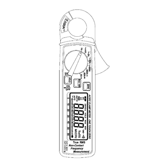
II. Panel Description 1. Transformer Jaw This is used to pick up current signal. To measure DC/AC current, conductor must be enclosed by the jaw. 2. Transformer Trigger This is used to open the jaw. 3. Function Selector Switch This is the on/off switch and used to select the function user desired, such as DCA, ACA, Hz. - Page 8 6. Zero/Relative Button Once this button is pressed, the current reading shall be set to zero and be used as a zero reference value for all other subsequent measurement. The function is also used to remove offset value caused by the residual magetism remained in the core for the DC current measurement.
-
Page 9: Operation Instructions
III. Operation Instructions 3.1 DC/AC Current Measurements 3.1.1 DC Current a. Set the rotary switch at appropriate DC range. b. Push the zero button to adjust the reading to zero. c. Press the trigger to open the jaw and fully enclose the conductor to be measured. -
Page 10: Frequency (Hz) Measurement
3.1.2 AC Current e. Set the rotary switch at appropriate AC range. f. Press the trigger to open the jaw and fully enclose the conductor to be measured. No air gap is allowed between the two half jaws. g. Read the ACA value from the LCD display. 3.2 Frequency (Hz) Measurement h. -
Page 11: Relative Reading Measurements
3.3 Relative Reading Measurements The zero button also can be used to make a relative measurement. Once the button is pushed, the current reading is set to zero and a zero symbol shall be displayed on LCD. All the subsequent measurement shall be displayed as a relative value with respect to the value being zeroed. -
Page 12: Specifications
IV. Specifications(23 C±5 C) DC Current: Range Resolution Accuracy Overload Protection ±1.0%±3dgts AC 700A 60A (0A~40A) 10mA ±1.0%±3dgts AC 700A 60A (40A~50A) 10mA ±2.0%±3dgts AC 700A 60A (50A~60A) 10mA ±2.5%±3dgts AC 700A 600A 100mA ±1.0%±3dgts AC 700A After measuring DC 600A, there will be about 700-digit residual magnetism when you measure 6A range (after pressing ZERO the measurement range will be 5.300A). - Page 13 Indoor Use Conductor Size: 23mm max. (approx.) Battery Type: two 1.5V SUM-3 Display: 3 5/6 LCD with seg. Bargraph Range Selection: manual Overload Indication: Power Consumption: 19-28 mA (approx.) Low battery Indication: Sampling Time: 3 times/sec. (display) 30 times/sec. (bargraph) Operating Temperature: -10 ...
-
Page 14: Battery Replacement
V. Battery Replacement When the low battery symbol is displayed on the LCD, replace the old batteries with two new batteries. A. Turn the power off and remove the test leads from the clamp meter. B. Remove the screw of the battery compartment. C.
Need help?
Do you have a question about the Pro True RMS CM-07 and is the answer not in the manual?
Questions and answers