
Related Manuals for Siemens SINEC L2


Summarization of Contents
How to Use This Manual
Conventions
Discusses document conventions and refers to other manuals.
Courses
Information about Siemens training courses.
Reference Material
Lists other relevant Siemens manuals and publications.
Safety-Related Guidelines for the User
Proper Usage
Guidelines on the correct application and operation of the equipment.
1 System Description
1.1 Communications in Industry
Overview of industrial communication systems and hierarchy levels.
1.2 The SINEC L2 Local Area Network
Explains the SINEC L2 LAN based on PROFIBUS standards.
Definitions
Defines terms like Planning Level, Process Control Level, Cell Level, Field Level.
Communication Tasks Required from the Different Networks
Compares network requirements for different levels.
1.3 Procedure for Accessing the SINEC L2 Network
Explains network access, station types (active/passive), and token passing.
Station Address
Discusses assigning unique addresses to each station on the bus.
Token / Right to Transmit
Explains how the token frame grants bus access rights.
Target Rotation Time
Time Management of the Network
Describes how the network manages time based on real vs. target rotation times.
Broadcasting
Defines broadcasting as sending a message to all stations.
Multicasting
Defines multicasting as sending to several stations.
1.4 Assigning Parameters for the L2 Interface of the S5-95U
DB1 with the Default Parameters for Standard Connections
Shows default DB1 parameters for standard connections.
Table 1-1. DB1 Basic Parameters
Table 1-2. Relevant Basic Parameters for the S5-95U as an Active/Passive Station
Shows parameter relevance for active vs. passive stations.
Rules for Setting the Basic Parameters
Communications with S5-95Us (homogeneous S5-95U networks)
Defines parameters for homogeneous networks.
Example: Communications with CP 5410, S5-95U and CP 5430-0
Example for setting parameters with specific communication processors.
Bit time unit
Explains how to calculate times from bit time units.
Communications with the CP 5410 and/or CP 5430-1
Communications with Other SIMATIC Devices, e.g. the CP 5412 or CP 5430-0
Parameter settings for communication with other SIMATIC devices.
1.5 Types of Data Transmission for the S5-95U
Is my S5-95U to be a passive or active station on the LAN?
Discusses the choice between passive and active station roles.
Which type of data transmission should I choose?
Guides selection of data transmission types based on tables.
Table 1-6. Recommended Types of Data Transmission
Recommends data transmission types based on application.
Selecting the Types of Data Transmission to Suit the Hardware Configuration
1. Communications between two S5-95Us
Describes PLC-to-PLC and Cyclic I/O connections between S5-95Us.
Standard connection (SC)
2. Communications between an S5-95U and a Device of Other Manufacture
Illustrates PLC-to-PLC and Cyclic I/O with external devices like CP 5430.
1.6 Physical Bus Characteristics and Installation Techniques for the SINEC L2 Network
1.6.1 RS 485 Transmission Technology
Details physical bus characteristics and related distances for RS 485.
The conditions for installing the network are as follows:
Table 1-10. Distance Table for RS 485 Technology
Shows distance tables for RS 485 technology based on baud rate and segments.
Installation Techniques
SINEC L2 Bus Connector
Details the SINEC L2 bus connector, its designs and installation.
Bus Terminals
Describes bus terminals with RS 485 technology as an alternative.
Bus Cable for SINEC L2
RS 485 SINEC L2 Repeater
Explains the use and types of RS 485 SINEC L2 repeaters.
1.6.2 Fiber Optics Transmission Technology
The conditions for installing the network are as follows:
Conditions for installing fiber optic networks.
Table 1-13. Distance Table for Glass Fiber Optic Cable Technology
Shows distances for glass fiber optic cable based on baud rate and star couplers.
Installation Techniques
Covers installation techniques for SINEC L2FO bus terminals.
2 Installation Guidelines
2.1 Basic Configuration
Illustrates main components of SINEC L2 in RS 485/S5-95U technology.
2.2 Installing a SINEC L2 Bus Segment
Note: Connecting terminals A and B for bus segments.
Notes on interconnecting terminals for bus segments.
2.3 Linking Bus Segments with the L2 Repeater
2.3.1 Electrical Design of the SINEC L2 Repeater RS 485
Discusses voltage potentials and isolation for EMC compliance.
Grounding Methods
Explains grounding methods for the repeater installation.
Reasons for Removing the Connecting Plate
Warning: Electric shock hazard voltage.
Warning about electric shock when removing the connecting plate.
2.3.2 Connecting the Supply Voltage
Details how to connect the supply voltage to the L2 repeater.
2.3.3 Connecting Bus Segments
Repeater at Segment End
Shows connection of two segments to a repeater at the end.
2.4 Routing Cables
Table 2-1. Limiting Conditions for Routing Cables Indoors
Lists conditions like bending radius and temperature range.
Lightning protection
Discusses lightning protection measures for outdoor cable routing.
Note: Lightning protection measures.
Advice on assessing and implementing lightning protection.
3 Start-Up, Tests, and Diagnostics
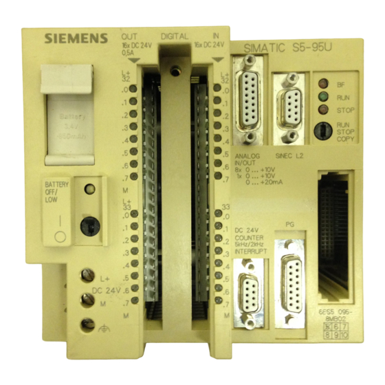
3.1 Design and Mode of Operation of the Programmable Controller
Explains the controller's displays, controls, and interfaces.
3.2 START-UP Sequence
Details the sequence of operations during system startup.
3.3 Starting Up a System
3.3.1 Suggestions for Configuring and Installing the Equipment
Offers recommendations for safe installation and configuration.
Operating the Programmable Controller with a SINEC L2 Interface
Communications Processor
Describes the tasks of the communications processor.
SINEC L2 Interface
Details the pin assignment for the SINEC L2 interface connector.
3.3.2 Prerequisites for Starting Up the S5-95U as a SINEC L2 Station
Parameter Assignments Required in DB1:
Lists required DB1 parameter settings for data transmission types.
3.3.3 System Startup Diagnostics and Procedures
Table 3-1. Interpretation of the BF LED Display
Maps BF LED states to causes and corrective actions.
Note: BF LED behavior with default DB1.
Explains BF LED behavior when using default DB1 settings.
Test Possibilities during Start-Up
Startup Procedure for the SINEC L2 station
Step-by-step procedure for starting up the L2 station.
3.4 FMA Services
3.4.1 Principle of Operation
Explains the basic operation of FMA services using L2-SEND/L2-RECEIVE.
3.4.2 The Types of FMA Services
Table 3-2. FMA Services Possible with the L2 Interface of the S5-95U
Lists available FMA services and their functions.
Table 3-3. Characteristics of FMA Services
Compares FMA services based on S5-95U state (active/passive) and requirement.
3.4.3 Assigning Parameters in DB1 for the FMA Services
Table 3-4. DB1 Parameters for the FMA Services
Lists DB1 parameters for FMA services (STB, FMAE).
3.4.4 Managing of all FMA Services with FB222
Structure the control program for the FMA services as shown in Figure 3-10.
Outlines the control program structure for FMA services using FB222.
Significance of the FB222 Parameters:
Explains input/output parameters for FB222 (REQ, CODE, CONF, INDI, FEHL).
3.4.5 Reading Out a List of All Active Stations on the Network (LAS_LIST_CREATE)
Table 3-5. link_status Messages for the LAS_LIST_CREATE Confirmation
Lists link_status messages for LAS_LIST_CREATE confirmation.
3.4.6 Reading the Status of Another Station (FDL_STATUS)
Table 3-6. link_status Messages for the FDL_STATUS Confirmation
Lists link_status messages for FDL_STATUS confirmation.
3.4.7 Reading Updated Bus Parameters (READ_VALUE)
Table 3-7. link_status Messages for the READ_VALUE Confirmation
Lists link_status messages for READ_VALUE confirmation.
3.4.8 Reading Out Available Token Hold Time When Receiving the Token (TIME_TTH_READ)
Table 3-9. link_status Messages for the TIME_TTH_READ Confirmation
Lists link_status messages for TIME_TTH_READ confirmation.
3.4.9 Reading Out the Event Message (MAC_EVENT)
Table 3-10. Event Parameter Message in Indication Block
Lists possible error codes, causes, and remedies for MAC_EVENT.
4 Data Transmission Using a Standard Connection
4.1 Features of a Standard Connection
Describes when standard connection is appropriate and its characteristics.
Principle of Operation
Figure 4-2. Functional Diagram of a Standard Connection
Illustrates the data flow for standard connections.
4.2 Assigning Parameters in DB1 of the S5-95U for Data Exchange with Standard Connections
Figure 4-3. DB1 with the Default Parameters for Standard Connections
Shows default DB1 parameters for standard connections.
Table 4-1. DB1 Parameters for Standard Connections
Lists and explains DB1 parameters for standard connections (SF, EF, KBS, KBE).
Example: Two S5-95U programmable controllers are to communicate using a standard connection.
Table 4-2. Setting Parameters for Standard Connections
Shows specific DB1 parameter settings for PLC 1 and PLC 2.
4.3 Transmitting Data
Figure 4-4. Structure of the Send Mailbox for a Standard Connection
Shows how information is stored in the send mailbox.
Structure of the Send Coordination Byte (CBS)
Warning: Bit 6 of CBS.
Warning about undefined conditions when writing to CBS bit 6.
4.4 Receiving Data
Figure 4-6. Structure of the Receive Mailbox for a Standard Connection
Shows how information is stored in the receive mailbox.
Structure of the Receive Coordination Byte (CBR)
Warning: Bit 6 of CBS.
Warning about bus entering undefined state if writing to CBS bit 6.
4.5 Programming Example for Data Transmission via a Standard Connection
Control program in FB1 for receiving data.
Flowchart for receiving data.
Control program in FB1 for transmitting data.
Flowchart for transmitting data.
Programmable Controller 1
Cyclical Program for Station 1 (Programmable Controller 1)
Details DB1 settings, OB1, and FB1 for PLC 1.
Programmable Controller 2
Cyclical Program for Station 2 (Programmable Controller 2)
Details DB1 settings, OB1, and FB105 for PLC 2.
4.6 Broadcast Request (“Transmit to All”)
The sender's prerequisites for broadcast transmission are as follows:
Lists prerequisites for the sender in broadcast transmission.
The receiver’s prerequisites for broadcast transmission are as follows:
Lists prerequisites for the receiver in broadcast transmission.
Note: Bits 1, 3, and 4 in the CBS are not relevant for broadcast jobs.
Notes on CBS bits relevance for broadcast.
5 Integral Standard Function Blocks L2-SEND and L2-RECEIVE
5.1 Parameters for L2-SEND and L2-RECEIVE
Lists parameters for L2-SEND (A-NR, QTYP, DBNR, QANF, QLAE).
Table 5-2. A List of Parameters Used by L2-RECEIVE (FB253)
Lists parameters for L2-RECEIVE (A-NR, ZTYP, DBNR, ZANF, ZLAE).
Table 5-3 Allocation of the Job Numbers
Allocates job numbers to communication services (PLC-PLC, Layer 2, FMA, Cyclic I/O).
The formal operands that have to be specified when the standard function blocks are used are explained in Tables 5-4 and 5-5.
Table 5-4. Formal Operands: Significance of the Parameters Used with L2-SEND (FB 252)
Details parameters like A-NR, QTYP, DBNR, QANF, QLAE for L2-SEND.
Table 5-5. Formal Operands: Significance of the Parameters Used with L2-RECEIVE (FB 253)
Details parameters like A-NR, ZTYP, DBNR, ZANF, ZLAE for L2-RECEIVE.
5.2 Direct and Indirect Parameter Settings for the L2 Function Blocks
Table 5-6. An Example of Direct Parameter Settings for the L2-SEND Function Block
Example of direct parameter settings for L2-SEND.
Table 5-7. An Example of Indirect Parameter Settings for the L2-SEND Function Block
Example of indirect parameter settings for L2-SEND.
5.3 Parameter Assignment Error Byte (PAFE)
Figure 5-2. Structure of the PAFE Parameter Assignment Error Byte
Shows the structure and error codes of the PAFE byte.
5.4 Status Byte
Figure 5-3. Structure of the Status Byte
Shows the structure of the status byte (STB) and length byte (LB).
Warning: Writing to the status byte.
Warning about writing to the status byte.
6 Data Transmission Using PLC-to-PLC Connections
6.1 Features of the PLC-to-PLC Connections
Describes characteristics of PLC-to-PLC connections.
Principle of Operation
Figure 6-2. Functional Diagram of a PLC-to-PLC Connection
Illustrates the data flow for PLC-to-PLC connections.
6.2 Assigning Parameters in DB1 of the S5-95U for Data Exchange with PLC-to-PLC Connections
Figure 6-3. Diagram: Data Transmission Using PLC-to-PLC Connections
Shows how DBs, STBs, and L2 FBs work together.
Table 6-1. Configuring Job Number n in DB1
Aid for assigning job numbers in DB1 for PLC-to-PLC connections.
DB1 Parameters for PLC-to-PLC Connections
Table 6-3. Assigning Parameters for PLC-to-PLC Connections
Shows specific DB1 parameter assignments for PLC 1 and PLC 2.
6.3 Programming Example for Data Transmission via PLC-to-PLC Connections Using Standard Function Blocks
Control program in FB105 for transmitting data.
Flowchart for transmitting data using FB105.
Control program in FB15 for receiving data.
Flowchart for receiving data using FB15.
Programmable Controller 1
Cyclical Program for Station 1 (Programmable Controller 1)
Details OB1, FB5, FB105, DB21, DB22 for PLC 1.
Programmable Controller 2
Cyclical Program for Station 2 (Programmable Controller 2)
Details OB1, FB5, FB105, DB21, DB22 for PLC 2.
7 Data Transmission Using Cyclic I/O
7.1 Features of Cyclic I/O
Describes characteristics of cyclic I/O (ZP) transmission.
Principle of Operation
Figure 7-1. Functional Diagram of Cyclic I/O
Illustrates the data flow for cyclic I/O.
Updating the Cyclic I/O Input Area and Output Area
SAP Number
Explains SAP addressing and its parameters in DB1.
Restart sequence when:
Details restart procedures after PLC reset or parameter changes.
ZP Safety Function
Explains behavior of ZP data during RUN to STOP transition and slave failure.
7.2 Assigning Parameters in DB1 of the S5-95U for Data Exchange with Cyclic I/O
Figure 7-2. Diagram: Data Transmission Using Cyclic I/O
Shows how DB1, STBs, and ZP DB work together for cyclic I/O.
Examples:
Figure 7-3. Division of the DB Reserved for Cyclic I/O (ZP) in the S5-95U (Example for ZP Master)
Shows ZP DB structure for ZP master.
Figure 7-4. Division of the DB Reserved for Cyclic I/O (ZP) in the S5-95U (Example for ZP Slave)
Shows ZP DB structure for ZP slave.
DB1 Parameters for Cyclic I/O
Table 7-1. DB1 Parameters for Cyclic I/O
Details parameters for ZP Master (ZPDB, ZPMS, ZPM, ZPLI) and ZP Slave (ZPDB, ZPSS, ZPSA, ZPSE).
Example: Four S5-95Us are to communicate using cyclic I/O.
Table 7-2. Assigning Parameters for Cyclic I/O
Shows specific DB1 parameter assignments for ZP master and ZP slaves.
ZP Slave Life List
Example: ZP slave life list is located in the flag area starting with flag byte FY2
Example of ZP slave life list in flag area.
Example: ZP slave life list is located in data block starting with data word DW2
Example of ZP slave life list in data block.
Figure 7-6. Structure of the ZP Slave Life List
Shows the structure of the ZP slave life list.
ZP Slave Watchdog
Table 7-3. ZP Slave “Response Time” for the S5-95U Calculated from the Baud Rate at a Given Slot Time
Lists ZP slave response times based on baud rate and slot time.
7.4 Programming Example for Data Transmission via Cyclic I/O
Cyclic Program for Station 1 (ZP Master)
Details OB1, FB202, DB202, DB100 for ZP master setup.
8 Data Transmission by Accessing Layer 2 Services
8.1 Characteristic Features of Layer 2 Access Data Transmission
Lists features like programming up to 23 accesses, data size, parallel operation, and use of L2-SEND/L2-RECEIVE.
8.2 Types and Characteristic Features of the Layer 2 Services
Table 8-1. Layer 2 Services of the L2 Interface of the S5-95U
Summarizes when to use each Layer 2 service and its applicability.
SAPs and Job Numbers
Figure 8-3. Using Job Numbers (A-NR) for Accessing Layer 2 Services via SAPs
Illustrates the interaction between STEP 5, SAPs, and job numbers.
8.3 Assigning the S5-95U Parameters for Data Communications
Defining the job numbers for a PLC ( chapter 5):
Explains how to define job numbers for L2-SEND and L2-RECEIVE.
Table 8-2. Defining Job Numbers in the L2 FBs
Lists job numbers and their usage for L2 FBs.
Figure 8-5. Schematic: Data Transmission Using Layer 2 Services
Shows interaction of DBs, STBs, and L2 FBs for Layer 2 data communication.
DB1 Parameters for Layer 2 Services
Table 8-3. Layer 2 Services, DB1 Parameters
Details parameters for STBS and STBR (SAP number, status byte location).
Table 8-4. Entering Parameters for Layer 2 Services
Shows example DB1 parameter entries for Layer 2 communication between S5-95Us.
8.4 FBs for Managing All Layer 2 Services
Structure of the Control Program for Sending the Request and Fetching the Confirmation in FB223
Flowchart for sending requests and fetching confirmations using FB223.
Structure of the Control Program for Fetching the Indication in FB224
Flowchart for fetching indications using FB224.
8.5 Sending Data to a Station (SDA Service)
Data transmission schematic ( Figure 8-6):
Illustrates data flow for SDA service.
Figure 8-6. Sending and Receiving Data with Acknowledgement or Confirmation (SDA)
Shows the process of sending and receiving data with SDA.
Figure 8-7. Structure of Requests, Confirmations and Indications for the SDA Service
link_status Message in the Confirmation Header
Lists link_status messages for SDA confirmation.
8.6 Sending Data to Several Stations (SDN)
Prerequisites for multicasting:
Lists prerequisites for multicasting (same SAP, global address).
Data transmission schematic ( Figure 8-8):
Illustrates data flow for SDN service.
Figure 8-8. Sending and Receiving Data without Acknowledgement or Confirmation (SDN)
Shows the process of sending and receiving data with SDN.
Figure 8-9. Structure of Requests, Confirmations and Indications for the SDN Service
link_status Message in the Confirmation Header
Lists link_status messages for SDN confirmation.
8.7 Holding Data for Fetching Once Only by a Station (RUP_SINGLE Service)
Before the sender requests data from the receiver (SRD layer 2 service)...
Explains receiver's role in keeping data ready.
Data holding procedure for the receiver ( Figure 8-10):
Illustrates data holding procedure for RUP_SINGLE.
Figure 8-10. Holding Data Ready for Fetching with the RUP_SINGLE Service
Shows the process for holding data for single fetch.
Figure 8-11. Request and Confirmation Structures for the RUP_SINGLE Service
link_status Message in the Confirmation Header
Lists link_status messages for RUP_SINGLE confirmation.
8.8 Holding Data Ready for Fetching Several Times Over by One or More Stations (RUP_MULTIPLE Service)
Before the sender requests data from the receiver (SRD layer 2 service)...
Explains receiver's role in keeping data ready using RUP_MULTIPLE.
Data holding procedure for the receiver ( Figure 8.12):
Illustrates data holding procedure for RUP_MULTIPLE.
Figure 8-12. Holding Data Ready for Fetching with the RUP_MULTIPLE Service
Shows the process for holding data for multiple fetches.
Figure 8-13. Request and Confirmation Structures for the RUP_MULTIPLE Service
link_status Message in the Confirmation Header
Lists link_status messages for RUP_MULTIPLE confirmation.
8.9 Sending Data and Fetching Data from a Station (SRD Service)
Prerequisite for data transmission:
States prerequisite of holding data ready using RUP_SINGLE or RUP_MULTIPLE.
Data transmission schematic ( Figure 8-14):
Illustrates data flow for SRD service.
Figure 8-14. Sending and Fetching Data with the SRD Service
Shows the process of sending data and fetching data with SRD.
Requesting Data (SRD Layer 2 Service without Send Data)
Figure 8-15. Structure of Requests, Confirmations and Indications for the SRD Service
Shows structures for SRD requests, confirmations, and indications.
9 Programmer Functions Over the SINEC L2 Network
9.1 Programmer Functions
Lists programmer functions usable over the SINEC L2 LAN.
Prerequisites:
Important: Programmer functions over the SINEC L2 LAN can only be implemented for active S5-95Us.
Highlights that programmer functions require active stations.
Note: PLC reset and SINEC L2 interface.
Explains behavior after PLC reset and how it affects programming.
Reason: Default DB1 validation after reset.
Explains why programming fails after reset due to default DB1.
Remedy: Overwriting comment characters and transferring DB1.
Provides steps to resolve programming issues after reset.
9.1 Programmer Functions
Table 9-1. Functions of a Programmer Operated as a SINEC L2 Station
Lists programmer functions and their availability over SINEC L2 LAN.
9.2 Selecting the L2 Interface
Figure 9-1. "INTERFACE SELECTION" Screen
Shows the interface selection screen.
9.3 Entering Defaults
Figure 9-2. The "FUNCTION SELECTION/DEFAULTS" Screen of the "BUS DIALLING" Utility
Shows the function selection screen for bus dialling.
9.4 Editing a Path
Figure 9-3. Path to be Edited with the "BUS DIALLING" Utility
Illustrates editing a path for SINEC L2 connection.
Note: "ENDP" and "CP L2" integration.
Notes on integrated processors in S5-95U for path editing.
Figure 9-4. Screen for Editing a Path (1)
Note: Deleting the last entered element.
Advice on deleting a path element.
Figure 9-5. Screen for Editing a Path (2)
Change the default address "0" ... to "2" ...
Instruction to change the address for reaching the S5-95U.
Press (ENDP) to complete the path.
Instruction to finalize path editing.
Confirm the path parameters with (SAVE).
Instruction to save the configured parameters.
Figure 9-6. Screen for Activating a Path (1)
Press (SYSID) to match the local LAN parameters...
Instruction to match local LAN parameters to system parameters.
9.5 Setting the L2 Basic Parameters on the Programmer
Figure 9-8. "SYSID CP L2 (LOCAL)" Screen
Shows the screen for setting local CP L2 parameters.
Appendix A DB1 Parameters, DB1 Parameter Assignment Errors, Calculation of Target Rotation Time
Basic Parameters for all Functions
Lists basic parameters like TLN, STA, BDR, HSA, TRT, SET, ST, SDT1, SDT2.
Parameters for FMA Services
Lists parameters for FMA services (STB, FMAE).
Parameters for Standard Connections
Lists parameters for standard connections (SF, EF, KBS, KBE).
DB1 Parameters, DB1 PAFE, TRT
Parameters for PLC to PLC Connection
Lists parameters for PLC to PLC connections (STBS, STBR).
Parameters for Cyclic I/O
Lists parameters for Cyclic I/O (ZPDB, ZPMS, ZPM, ZPLI for master; ZPDB, ZPSS, ZPSA, ZPSE for slave).
Calculating the Target Rotation Time
Table for calculating target rotation time (Token, SDN, SDA, SRD).
Provides frame types and baud rates for calculation.
Example of Calculating the Target Rotation Time
Tip to optimize the target rotation time:
Advice on optimizing target rotation time by assigning station addresses.
Appendix B SAP Numbers / Job Numbers
B SAP Numbers / Job Numbers
Defines terms and lists SAP numbers assigned by the system.
Appendix C List of Abbreviations/Glossary
C List of Abbreviations/Glossary
Lists LAN mnemonics and their explanations.
LAN-Specific Mnemonic Explanation
LAN-Specific Mnemonic Explanation
Continues the list of LAN mnemonics and their explanations.
Glossary
Glossary (continued)
Continues definitions of terms.
Glossary (continued)
Continues definitions of terms.
Glossary (continued)
Continues definitions of terms.
Glossary (continued)
Continues definitions of terms.
Appendix D List of Accessories and Order Numbers
D List of Accessories and Order Numbers
Lists S5-95U controller, manual, interface, and bus accessories with order numbers.
Appendix E Technical Specifications; Cycle Delay Times of the PLC Caused by SINEC L2 Operations
Climatic Environmental Conditions
Refers to S5-90U/S5-95U System Manual for environmental conditions.
Mechanical Environmental Conditions
Refers to S5-90U/S5-95U System Manual for mechanical conditions.
Electromagnetic Compatibility (EMC), Noise Immunity
Refers to S5-90U/S5-95U System Manual for EMC.
IEC-/VDE Information
Refers to S5-90U/S5-95U System Manual for IEC/VDE info.
Internal Technical Specifications
Details power supply, output voltage/current, and back-up battery.
Worst Case PLC Delay Time caused by SINEC L2
Lists PLC delay times for standard, PLC-to-PLC, and cyclic I/O operations.
Data Specific to SINEC L2
Lists main processor, communications processor, and bus cable details.
SINEC L2 Communications Services
Details data amounts, addresses, and broadcast availability for various services.
SINEC L2 Communications Services (Continued)
Continues specifications for Layer 2 Services, FMA Services, and Programmer Functions.
Integral Blocks
Lists integral organization blocks and function blocks.
Need help?
Do you have a question about the SINEC L2 and is the answer not in the manual?
Questions and answers