Sign In
Upload
Download
Table of Contents
Contents
Add to my manuals
Delete from my manuals
Share
URL of this page:
HTML Link:
Bookmark this page
Add
Manual will be automatically added to "My Manuals"
Print this page
×
Bookmark added
×
Added to my manuals
Manuals
Brands
KB Electronics Manuals
Controller
KBDA-27D
Installation and operation manual
KB Electronics KBDA-27D Installation And Operation Manual
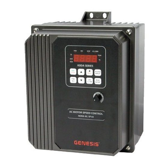
K4 series. adjustable frequency drives for 3-phase ac motor nema-4x / ip-65
Hide thumbs
1
Table Of Contents
2
3
4
5
6
7
8
9
10
11
12
13
14
15
16
17
18
19
20
21
22
23
24
25
26
27
28
29
30
31
32
33
34
35
36
37
38
39
40
41
42
43
44
45
46
47
48
49
50
51
52
53
54
55
56
page
of
56
Go
/
56
Contents
Table of Contents
Bookmarks
Table of Contents
Table of Contents
Quick-Start Instructions
Quick-Start Connection Diagram
Safety Warning
Introduction
Optional Accessories
General Performance Specifications
Electrical Ratings
Keypad Layout with Main Speed Potentiometer
Model KBDA-24D Drive Layout
Model KBDA-27D Drive Layout
Models KBDA-29, 45, 48 Drive Layout
Model KBDA-24D Mechanical Specifications
Models KBDA-27D, 29, 45, 48 Mechanical Specifications
Important Application Information
Maximum Allowed Motor Torque Vs. Speed
Open Ventilated Motor with External Fan Cooling
Mounting Instructions
Electrical Connections
Drive Terminal Block Wire and Tightening Torque Specifications
Models KBDA-24D, 27D AC Line Input, Motor, and Ground Connections
Multi-Function Output Relay Contacts
Multi-Function Output Relay "Run" and "Fault" Operating Modes
Models KBDA-29, 45, 48 AC Line Input, Motor, and Ground Connections
Model KBDA-27D AC Line Input Voltage Selection (Jumper J1)
Model KBDA-24D AC Line Input Voltage Selection (Jumper J1)
AC Line Input Voltage Selection (Jumper J1 (Models KBDA-24D, 27D Only))
Recommended High Voltage Dielectric Withstand Testing (Hi-Pot Testing)
Typical Hi-Pot Test Setup
Drive Operation
Keypad Description
Flow Chart to Program the Drive for 50 Hz Motors
Flow Chart to Program Motor Current from 6.7 Amps to 5.5 Amps
Flow Chart to Change Set Frequency from 5.00 Hz to 43.21 Hz
Flow Chart to Program Accel Time from 1.5 Seconds to 120 Seconds
Flow Chart to Program the Drive to Display Motor RPM
Flow Chart to Program the Drive to Display Custom Units "012.0
Flow Chart Showing Motor Current, Motor Voltage, and Bus Voltage Added to the Basic Display
Digital Readout Codes
Function No. Description
Programmable Function Summary List
Model Software Revision Codes
Diagnostic Leds
LED Descriptions
Appendix A - Optional IODA Input/Output Multi-Function Board
IODA Status Indicator LED
IODA Layout (All Models)
IODA Terminal Block TB1 Layout
IODA Terminal Block TB1 Wire and Tightening Torque Specifications
IODA Functions and Features
Preset Frequency Selection Switch or Contact Connections and Function Settings
Preset Frequency Selection
Up/Down Frequency Control Switch or Contact Connections and Function Settings
Accel/Decel 2 Switch or Contact Connection and Function Settings
Forward/Stop-Reverse/Stop Switch or Contact Connections and Function Settings
External Fault Auxiliary Equipment Switch or Contact Connection and Function Setting
Reset Switch or Contact Connection and Function Setting
32 2-Wire Start/Stop Switch or Contact Connection and Function Settings
33 3-Wire Start/Stop Switch or Contact Connection and Function Settings
Analog Input 1 Signal Voltage Following Connection and Function Settings
Analog Input 2 Signal Current Following Connection and Function Settings
Analog Input 1 Electrical Ratings
Analog Input 2 Electrical Ratings
Analog Outputs 1 and 2 Connections and Function Settings
Analog Outputs 1 and 2 Electrical Ratings
Bidirectional Motor Operation Main Speed Potentiometer Connection and Function Setting
Multi-Function Output Relay Contacts Connections and Function Settings
Multi-Function Open Collector Connections and Function Settings
Multi-Function Open Collector Outputs Electrical Ratings
Limited Warranty
Advertisement
Quick Links
1
Quick-Start Instructions
2
Digital Readout Codes
3
Programmable Function Summary List
Download this manual
K 4 S E R I E S ( K B D A )
Table of
Contents
Previous
Page
Next
Page
1
2
3
4
5
Advertisement
Table of Contents
Need help?
Do you have a question about the KBDA-27D and is the answer not in the manual?
Ask a question
Questions and answers
Subscribe to Our Youtube Channel
Related Manuals for KB Electronics KBDA-27D
Controller KB Electronics KBDA-24D Installation And Operation Manual
K4 series. adjustable frequency drives for 3-phase ac motor nema-4x / ip-65 (56 pages)
Controller KB Electronics KBVF-21D Installation And Operation Manual
Kbvf series chassis / ip-20 inverters, variable speed / soft-start ac motor dri (20 pages)
Table of Contents
Save PDF
Print
Rename the bookmark
Delete bookmark?
Delete from my manuals?
Login
Sign In
OR
Sign in with Facebook
Sign in with Google
Upload manual
Upload from disk
Upload from URL


Need help?
Do you have a question about the KBDA-27D and is the answer not in the manual?
Questions and answers