Samsung ML-2510 series Service Manual
Ml-2500 series
Hide thumbs
Also See for ML-2510 series:
- User manual (170 pages) ,
- Manual del usuario (84 pages) ,
- Specifications (12 pages)
Table of Contents
Advertisement
Quick Links
SERVICE
LASER PRINTER
ML-2571N
LASER PRINTER
ML-2500 Series
ML-25 10/XAA
Basic Model : ML-2571N
Manual
The keynote of Product
- Speed : 25ppm (Ltr) / 24ppm(A4), 600dpi
- Paper Path : MPF Type Cassette
- Emulation : SPL (ML-2510)
PCL (ML-2570/ML-2571N)
- Processor : 150MHz Jupiter4e CPU
400MHz SPGP V
3
- Memory : ML-2510(SDRAM, 8MB),
ML-2570/2571N(SDRAM, 32MB)
- MP Cassette : 250 pages / Face Down
(100 pages)
- Fuser Design : Lamp Type
- I/O : ML-2510(USB1.1+IEEE 1284),
ML-2570/2571N(USB2.0+IEEE 1284)
- Machine Life : 50K(pages)
CPU
Advertisement
Table of Contents

Related Manuals for Samsung ML-2510 series


Summarization of Contents
Precautions
Safety Warning
Essential safety warnings for qualified service, no rebuilding, and laser safety compliance.
Safety Caution
Precautions regarding noxious toner material and avoiding electric shock or fire hazards.
Handling Precautions
Guidelines for machine installation, operation, and handling to prevent damage and harm.
Assembly/Disassembly Precautions
Essential guidelines for safe component replacement and disassembly, including cable routing.
ESD Precautions
Procedures to prevent static electricity damage to sensitive electronic components during service.
Product Specifications
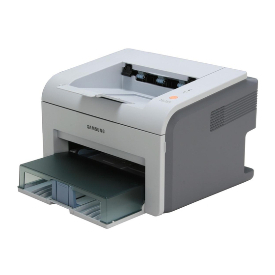
Product Overview
General description of the ML-2571N, ML-2510, and ML-2570 series printers.
Specifications
Detailed technical specs: print method, speed, resolution, media handling, and machine life.
Model Comparison Table
Comparison of ML-2510, ML-2570, and ML-2571N models' features and specifications.
Accessory
List of accessories included with the ML-2510 and ML-2570/2571N models.
System Overview
System Outline
Diagram and description of the printer's paper path layout and key components.
H/W Structure and Descriptions
Overview of the printer's hardware structure, including Main Control, SMPS, and HVPS.
S/W Structure and Descriptions
Introduction to Engine Control Firmware (F/W) for LBP engine operations and its architecture.
Initial Product Installation
Guides for installing printer software and system requirements, plus setup procedures.
Alignment and Adjustments
Sample Pattern
Use of sample patterns for maintenance and checking product abnormalities.
Control Panel
Illustration of the operational panel, identifying LEDs and buttons.
Consumables and Replacement Parts
Guideline for replacement cycle of consumables like rollers and toner cartridge.
Periodic Defective Image
Lists defective images and causes related to roller condition and specifications.
How to use DCU
Procedure to connect and set up the DCU for printer malfunction examination.
Paper Path
Illustration of paper path, detailing jam detection points and clearing procedures.
Disassembly and Reassembly
General Precautions on Disassembly
Emphasizes extreme caution during disassembly, proper cable routing, and using authorized components.
Disassembly and Reassembly
Detailed steps for disassembling major printer components like covers, SMPS, HVPS, and fuser.
Troubleshooting
Checking Symptoms
Guides on diagnosing printer problems by checking power, LEDs, paper path, and print quality.
Bad discharge
Troubleshooting common issues like wrong print position, paper jams (JAM 0, 1, 2), and multi-feeding.
Malfunction
Addresses malfunctions like LED blinking errors, paper empty issues, and cover open errors.
Bad Software Environment
Troubleshooting printer not working or abnormal printing due to software or environment setup issues.
Bad image
Diagnoses and resolves image defects: lines, bands, spots, light/dark images, ghosting, and stains.
Exploded Views & Parts List
Main Assembly
Exploded view and parts list for the printer's main assembly.
Frame Assembly
Exploded view and parts list for the printer's frame assembly.
Fuser Unit
Exploded view and parts list for the fuser unit.
Paper Path Assembly
Exploded view and parts list for the paper path assembly.
RX_Drive
Exploded view and parts list for the printer's RX drive mechanism.
Block diagram
ML-2510 H/W Block Diagram
Hardware block diagram for the ML-2510 printer.
ML-2570/2571N H/W Block Diagram
Hardware block diagram for the ML-2570/2571N printers.
Connection Diagram
ML-2510 Connection Diagram
Connection diagram for the ML-2510 printer, illustrating component interconnections.
ML-2570/2571N Connection Diagram
Connection diagram for the ML-2570/2571N printers, detailing component links.
Reference Information
Troubleshooting Tool
List of recommended tools for safe and easy troubleshooting of printer issues.
Acronyms and Abbreviations(1)
Explanation of abbreviations and acronyms used throughout the service manual.
Selecting printer locations
Guidance on selecting appropriate printer installation locations, considering ventilation and environment.
Sample Tests Patterns
Sample test patterns used for evaluating toner cartridge life and printing speed.
Circuit Description
Engine Controller
Description of the engine controller module: motor, PWM, LSU, and ADC controllers.
Heater Control
Explanation of the circuit controlling the fuser's heat lamp operation via TRIAC.
PWM Controller
Details of the PWM controller's functions and organization into sub-blocks for timer operations.
Motor Driver
Explanation of the motor drive circuit and IC used for controlling motor speed and current.
LSU Controller
LSU controller interface between PVC and LSU, including sync signals and rotation status.
ADC Controller
ADC controller function in converting analog signals and providing interrupt notifications.
Need help?
Do you have a question about the ML-2510 series and is the answer not in the manual?
Questions and answers