Table of Contents
Advertisement
Quick Links
SERVICE
LASER PRINTER
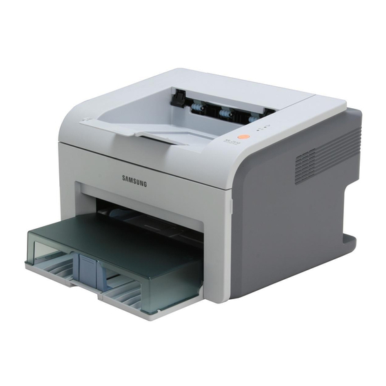
ML-2571N
LASER PRINTER
ML-2500 Series
ML-25 10/XAA
Basic Model : ML-2571N
Manual
The keynote of Product
- Speed : 25ppm (Ltr) / 24ppm(A4), 600dpi
- Paper Path : MPF Type Cassette
- Emulation : SPL (ML-2510)
PCL (ML-2570/ML-2571N)
- Processor : 150MHz Jupiter4e CPU
400MHz SPGP V
3
- Memory : ML-2510(SDRAM, 8MB),
ML-2570/2571N(SDRAM, 32MB)
- MP Cassette : 250 pages / Face Down
(100 pages)
- Fuser Design : Lamp Type
- I/O : ML-2510(USB1.1+IEEE 1284),
ML-2570/2571N(USB2.0+IEEE 1284)
- Machine Life : 50K(pages)
CPU
Advertisement
Table of Contents


Need help?
Do you have a question about the ML-2571N and is the answer not in the manual?
Questions and answers