
Related Manuals for Miller Blue Thunder 443


Summary of Contents for Miller Blue Thunder 443
- Page 1 OM-233 381C 2007−09 Processes Stick (SMAW) Welding Description Arc Welding Power Source Blue Thunder Series Models: 253, 343, 403, 443 Visit our website at www.MillerWelds.com...
- Page 2 We know you don’t have time to do it any other way. That’s why when Niels Miller first started building arc welders in 1929, he made sure his products offered long-lasting value and superior quality.
-
Page 3: Table Of Contents
TABLE OF CONTENTS SECTION 1 − SAFETY PRECAUTIONS - READ BEFORE USING ........1-1. - Page 4 20098 San Giuliano Milanese, Italy Phone: 39(02)98290-1 Fax: 39(02)98290203 European Contact Signature: Blue Thunder 253, 343, 403, 443 Declares that this product: conforms to the following Directives and Standards: Directives Low Voltage Directive: 73/23/EEC, 2006/95/EC Electromagnetic Compatibility Directives: 89/336/EEC, 92/31/EEC, 2004/108/EC...
-
Page 5: Section 1 − Safety Precautions - Read Before Using
SECTION 1 − SAFETY PRECAUTIONS - READ BEFORE USING som _2007−04 Protect yourself and others from injury — read and follow these precautions. 1-1. Symbol Usage DANGER! − Indicates a hazardous situation which, if Indicates special instructions. not avoided, will result in death or serious injury. The possible hazards are shown in the adjoining symbols or explained in the text. - Page 6 D Do not use welder to thaw frozen pipes. FUMES AND GASES can be hazardous. D Remove stick electrode from holder or cut off welding wire at contact tip when not in use. Welding produces fumes and gases. Breathing D Wear oil-free protective garments such as leather gloves, heavy these fumes and gases can be hazardous to your shirt, cuffless trousers, high shoes, and a cap.
-
Page 7: Additional Symbols For Installation, Operation, And Maintenance
1-3. Additional Symbols For Installation, Operation, And Maintenance FIRE OR EXPLOSION hazard. MOVING PARTS can cause injury. D Do not install or place unit on, over, or near D Keep away from moving parts such as fans. combustible surfaces. D Keep all doors, panels, covers, and guards D Do not install unit near flammables. -
Page 8: California Proposition 65 Warnings
1-4. California Proposition 65 Warnings For Gasoline Engines: Welding or cutting equipment produces fumes or gases which contain chemicals known to the State of California to Engine exhaust contains chemicals known to the State of cause birth defects and, in some cases, cancer. (California California to cause cancer, birth defects, or other reproduc- Health &... -
Page 9: Section 2 − Definitions
SECTION 2 − DEFINITIONS 2-1. Warning Label Definitions (For Wordless Labels) Warning! Watch Out! There are possible hazards as shown by the symbols. Electric shock from welding electrode or wiring can kill. 1.1 Wear dry insulating gloves. Do not touch electrode with bare hand. -
Page 10: Weee Label (For Products Sold Within The Eu)
Warning! Watch Out! There are possible hazards as shown by the symbols. Electric shock from wiring can kill. Disconnect input plug or power before working on machine. Read the Owner’s Manual before working on this machine. Consult rating label for input power requirements, and check power available at the job site −... -
Page 11: Manufacturer's Rating Label
2-3. Manufacturer’s Rating Label OM-233 381 Page 7... -
Page 12: Symbols And Definitions
2-4. Symbols And Definitions Negative Weld Positive Weld Protective Earth Amperes Output Terminal Output Terminal (Ground) Supplementary Output Protector Shielded Metal Arc Volts Input Remote Welding (SMAW) Three Phase Constant Current Rated Supply Transformer Duty Cycle (CC) Current Rectifier Rated No-Load Rated Supply Fuse Line Connection... -
Page 13: Section 3 − Installation
SECTION 3 − INSTALLATION 3-1. Specifications Amperes Input at Ampere Dimensions Rated Welding Rated Load Output, Range Open-Circuit (mm) Model KVA/KW Weight Output Rating 50/60 Hz, Three-Phase Voltage DC Voltage DC L x W x H L x W x H 230 V 380 V 400 V 520 V 220 A @ 29 Volts DC,... -
Page 14: Duty Cycle And Overheating
3-3. Duty Cycle and Overheating Duty Cycle is percentage of 10 min- utes that unit can weld at rated load without overheating. If unit overheats, thermostat(s) opens, output stops, and cooling fan runs. Wait fifteen minutes for unit to cool. Reduce amperage or duty cycle before welding. -
Page 15: Selecting A Location
3-4. Selecting A Location Lifting Eye Lifting Forks Use lifting eye or lifting forks to move unit. Movement If using lifting forks, extend forks beyond opposite side of unit. Rating Label Use rating label to determine input power needs. Line Disconnect Device Locate unit near correct input pow- er supply. -
Page 16: Weld Output Terminals And Selecting Cable Sizes
3-6. Weld Output Terminals and Selecting Cable Sizes Total Cable (Copper) Length In Weld Circuit Not Exceeding 150 ft 200 ft 250 ft 300 ft 350 ft 400 ft Weld Output 100 ft (30 m) Or Less (45 m) (60 m) (70 m) (90 m) (105 m) -
Page 17: Positioning Jumper Links
3-8. Positioning Jumper Links Check input voltage available at site. 230/400 Volt Models Jumper Links Access Remove side panel. 230 V 400 V Jumper Link Label Check label − only one is on unit. Input Voltage Jumper Links Move jumper links to match input voltage. -
Page 18: Connecting Input Power
3-10. Connecting Input Power Installation must meet all Na- tional and Local Codes − have only qualified persons make this installation. Disconnect and lockout/tag- out input power before con- necting input conductors from unit. Always connect green or green/yellow conductor to supply grounding terminal GND/PE first, and never to a line ter-... -
Page 19: Section 4 − Operation
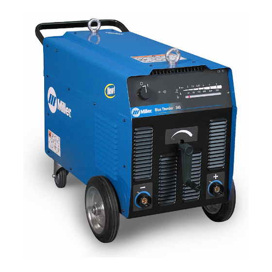
SECTION 4 − OPERATION 4-1. Controls Welding Current Indicator Weld Current Control + Positive Weld Terminal − Negative Weld Terminal Power On-Off Switch Power On Pilot Light 804 944 Notes Work like a Pro! Pros weld and cut safely. Read the safety rules at the beginning of this manual. -
Page 20: Section 5 − Maintenance And Troubleshooting
SECTION 5 − MAINTENANCE AND TROUBLESHOOTING 5-1. Routine Maintenance Disconnect power before maintaining. n = Check Z = Change ~ = Clean l = Replace * To be done by Factory Authorized Service Agent Every Months l Damaged Or l Cracked Weld cables ~n Weld Connections Unreadable Labels Every... -
Page 21: Section 6 − Electrical Diagrams
SECTION 6 − ELECTRICAL DIAGRAMS S9215019 Figure 6-1. Circuit Diagram For Blue Thunder 253 OM-233 381 Page 17... - Page 22 S9215018 Figure 6-2. Circuit Diagram For Blue Thunder 343 And 443 Models (380/520 V) OM-233 381 Page 18...
- Page 23 S9215023 Figure 6-3. Circuit Diagram For Blue Thunder 343 And 443 Models (230/400 V) OM-233 381 Page 19...
- Page 24 S9215020 Figure 6-4. Circuit Diagram For Blue Thunder 403 OM-233 381 Page 20...
- Page 25 Notes Work like a Pro! Pros weld and cut safely. Read the safety rules at the beginning of this manual. OM-233 381 Page 21...
-
Page 26: Section 7 − Parts List
SECTION 7 − PARTS LIST Hardware is common and not available unless listed. 804 964 Figure 7-1. Blue Thunder 253 OM-233 381 Page 22... - Page 27 Dia. Item Part Mkgs. Description Quantity Figure 7-1. Blue Thunder 253 ....+156121032 . . . Upper Panel ..........
- Page 28 Hardware is common and not available unless listed. 804 963 Figure 7-2. Blue Thunder 343 OM-233 381 Page 24...
- Page 29 Item Dia. Part Description Quantity Mkgs. Figure 7-2. Blue Thunder 343 ....+156121032 . . . Upper Panel ..........
- Page 30 Hardware is common and not available unless listed. 804 963 Figure 7-3. Blue Thunder 403 OM-233 381 Page 26...
- Page 31 Dia. Item Part Mkgs. Description Quantity Figure 7-3. Blue Thunder 403 ....+156121032 . . . Upper Panel ..........
- Page 32 Hardware is common and not available unless listed. 804 962 Figure 7-4. Blue Thunder 443 OM-233 381 Page 28...
- Page 33 Item Dia. Part Description Quantity Mkgs. Figure 7-4. Blue Thunder 443 ....+156121033 . . . Upper Panel ..........
- Page 34 Notes Work like a Pro! Pros weld and cut safely. Read the safety rules at the beginning of this manual.
- Page 35 Effective January 1, 2007 This limited warranty supersedes all previous Miller warranties and is exclusive with no other guarantees or warranties expressed or implied. LIMITED WARRANTY − Subject to the terms and conditions 1 Year — Parts and Labor Unless Specified below, ITW Welding Products Italy warrants to its original retail DC 253 &...
- Page 36 File a claim for loss or damage during Phone: 39 (0) 2982901 Fax: 39 (0) 298290-203 shipment. email: miller@itw−welding.it For assistance in filing or settling claims, contact your distributor and/or equipment manufacturer’s Transportation Department. © PRINTED IN USA 2007 Miller Electric Mfg. Co. 1/07...
Need help?
Do you have a question about the Blue Thunder 443 and is the answer not in the manual?
Questions and answers