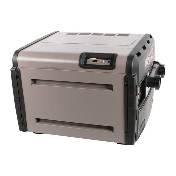
Summarization of Contents
Safety Precautions
High Voltage Electrocution Hazard
Warning about hazardous voltage and steps to reduce risk of shock.
Control Board and Fuse Layout
Integrated Control Board Layout (ICB)
Detailed diagram and labeling of the Integrated Control Board components.
Fuse Circuit Board Layout (Older Style)
Diagram and explanation of the older style fuse board configuration.
Fuse Circuit Board Layout (Newer Style)
Diagram and explanation of the newer style fuse board configuration.
UHS Operation Sequence
UHS Sequence of Operation: Normal
Step-by-step description of the heater's normal operating sequence.
UHS Sequence of Operation: Failure to Light
Steps taken by the heater when it fails to ignite successfully.
Electrical and Gas Connections
UHS Electrical & Gas Connection
Overview of electrical and gas connection points on the heater.
Electrical & Control Connections (Newer Style)
Details on newer style electrical and control connection configurations.
Electrical & Control Connections (Older Style)
Details on older style electrical and control connection configurations.
How-To Guides
Program Heater Bypass Operation
Instructions for placing the heater in bypass mode for external control.
Program Temperature Lock-Out
Instructions for setting temperature limits to lock out specific ranges.
Test/Adjust Gas Pressure
Procedures for measuring and adjusting gas pressure for optimal performance.
Troubleshooting
Diagnostic Codes
List of diagnostic codes and their meanings for troubleshooting.
Troubleshooting Part Numbers
List of replacement part numbers for troubleshooting common issues.
Heater Not Powering Up
Step-by-step troubleshooting for heaters that do not power on.
Open FC1 &/or F2 Fuse
Troubleshooting steps for open FC1 and/or F2 fuses.
Open FC3 &/or F1 Fuse
Troubleshooting steps for open FC3 and/or F1 fuses.
Open FC4 Fuse
Troubleshooting steps for an open FC4 fuse.
Service LED ON: 'BD' Code
Troubleshooting steps for the 'BD' diagnostic code.
Service LED ON: “EE” OR “CE” Code
Troubleshooting steps for 'EE' or 'CE' diagnostic codes.
Service LED ON: “IO” OR “SB” Code
Troubleshooting steps for 'IO' or 'SB' diagnostic codes.
Service LED ON: “SF” OR “HS” Code
Troubleshooting steps for 'SF' or 'HS' diagnostic codes.
Service LED ON: “PF” Code
Troubleshooting steps for the 'PF' diagnostic code.
Service LED ON: “HF” Code
Troubleshooting steps for the 'HF' diagnostic code.
Service LED ON: “LO” Code
Troubleshooting steps for the 'LO' diagnostic code.
Service LED ON: “IF” Code
Troubleshooting steps for the 'IF' diagnostic code.
Service LED ON: “AC” Code
Troubleshooting steps for the 'AC' diagnostic code.
Service LED ON: “AO” Code
Troubleshooting steps for the 'AO' diagnostic code.
Heat Exchanger Information
Heat Exchanger: Flow Requirements
Required water flow rates for proper heat exchanger operation.
Heat Exchanger: Inspection
Procedure for inspecting the heat exchanger for damage or blockages.
Heat Exchanger: Potential Failure Causes
Visual guide to common causes of heat exchanger failure.
Wiring Diagrams
FD General Wiring Schematic
Schematic diagram for the FD General model wiring.
Wiring Connection Diagram
Detailed wiring diagram for the heater, including component connections.


Need help?
Do you have a question about the H150FDP and is the answer not in the manual?
Questions and answers