Table of Contents
Advertisement
GESTRA Steam Systems
BA 46
BA 46-ASME
BA 47
BA 47-ASME
BAE 46...
BAE 46...-ASME
BAE 47...
BAE 47...-ASME
Installation Instructions / Product Information
818609-03
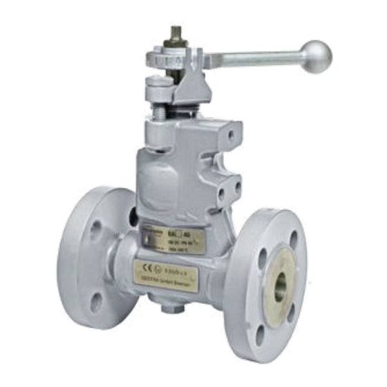
Continuous Blowdown Valve
BA 46 / BA 46-ASME, PN 40/ CL 150/300, DN 15-DN 50
BA 47 / BA 47-ASME, PN 63/ CL 600, DN 25, 40, 50
BAE 46... / BAE 46...-ASME, PN 40/ CL 150/300, DN 15-DN 50
BAE 47... / BAE 47...-ASME, PN 63/ CL 600, DN 25, 40, 50
EN
English
1
Advertisement
Table of Contents

Related Manuals for GESTRA BAE 47...


Summarization of Contents
Important Notes
Usage for the Intended Purpose
Defines the proper use of BA 46, BA 47, and BAE series continuous blowdown valves.
Safety Note
Emphasizes installation and maintenance by qualified personnel for safe operation.
Danger Warnings
Highlights risks of burns, cuts, bruising, and electric shock during operation and maintenance.
PED Compliance
Details compliance with the Pressure Equipment Directive (PED 97/23/EC).
ATEX Hazardous Area Compliance
Specifies conditions for using valves in potentially explosive areas as per ATEX directives.
Declaration of Conformity Information
Provides details on conformity assessments and manufacturer information.
Explanatory Notes
Scope of Supply
Lists all items included in the product packages for BA 46, BA 47, and BAE series valves.
Product Description
Explains the function and application of continuous blowdown valves in steam boiler plants.
Valve Functionality
Describes the operational mechanisms and control methods for BA and BAE valves.
Technical Data
Name Plate and Marking
Details information indicated on the valve's nameplate per EN 19 standards.
Dimensions BA 46, BA 47
Provides dimensional drawings and measurements for BA 46 and BA 47 valves.
Dimensions BAE 46, BAE 47
Shows dimensional drawings and measurements for BAE 46 and BAE 47 valves with actuators.
Flanged End Dimensions
Lists dimensions for flanged end connections according to EN and ASME standards.
Butt-Weld End Dimensions
Details dimensions for butt-weld end connections as per DIN and ASME standards.
Socket-Weld End Dimensions
Specifies dimensions for socket-weld end connections according to DIN and ASME standards.
Pressure and Temperature Ratings
Details maximum pressure and boiling point temperatures for various valve types.
Materials of Construction
Lists the materials used for key valve components in DIN/EN and ASTM specifications.
Actuator Specifications
Provides technical data for ARIS actuators EF 0.7 and EF 10, including dimensions and voltage.
Capacity Charts DN 15-32 Overview
An overview chart showing capacity ranges versus differential pressure for DN 15-32 valves.
Capacity Chart DN 15-32 (Up to 310 kg/h)
Specific capacity chart for DN 15-32 valves with a range up to 310 kg/h.
Capacity Chart DN 15-32 (Up to 1020 kg/h)
Specific capacity chart for DN 15-32 valves with a range up to 1020 kg/h.
Capacity Chart DN 15-32 (Up to 2120 kg/h)
Specific capacity chart for DN 15-32 valves with a range up to 2120 kg/h.
Capacity Charts DN 40-50 Overview
An overview chart showing capacity ranges versus differential pressure for DN 40-50 valves.
Capacity Chart DN 40-50 (Up to 1340 kg/h)
Specific capacity chart for DN 40-50 valves with a range up to 1340 kg/h.
Capacity Chart DN 40-50 (Up to 4500 kg/h)
Specific capacity chart for DN 40-50 valves with a range up to 4500 kg/h.
Capacity Chart DN 40-50 (Up to 6300 kg/h)
Specific capacity chart for DN 40-50 valves with a range up to 6300 kg/h.
Design
BA 46, BA 47 Valve Components
Exploded view diagram illustrating the components of BA 46 and BA 47 valves.
BAE 46, BAE 47 Valve with Actuator
Exploded view diagram showing BAE 46/47 valves with their associated actuators.
Design Key and Part Identification
A key listing and identifying all numbered parts shown in the design diagrams.
Installation
Flanged Connection Installation
Instructions for installing valves with flanged end connections.
Butt-Weld Connection Installation
Instructions for installing valves with butt-weld end connections.
Socket-Weld Connection Installation
Instructions for installing valves with socket-weld end connections.
Weld Heat Treatment
Guidance on required heat treatment procedures for welds after installation.
Repositioning the Control Lever
Procedure to rotate the control lever by 180° for improved visibility.
Installing the Sampling Valve
Steps for attaching an optional sampling valve to the blowdown valve.
Electrical Connection
BAE Series Actuator Operation
Explains operating positions and feedback potentiometer function for BAE actuators.
BAE Series Actuator Factory Settings
Details default settings for EF 0.7, EF 10, EF 0.7-1, and EF 10-1 actuators.
Commissioning Procedure
Boiler Blowdown Calculation
Provides formula and example for calculating the required boiler blowdown rate.
Manual Blowdown Adjustment (BA 46/47)
Describes manual adjustment of blowdown using the control lever on BA 46/47 valves.
Automated Blowdown Control (BAE Series)
Explains setting TDS levels via control equipment for BAE series automated blowdown.
Operation
Purging Procedure
Instructions for periodically opening the blowdown valve to purge it.
Emergency Operation for BAE Series
Procedure for manual emergency operation of BAE series valves without power.
Maintenance
Changing Internals of BA 46, BA 47
Detailed steps for disassembling and replacing internal parts of BA 46/47 valves.
Changing Internals of BAE 46, BAE 47
Detailed steps for disassembling and replacing internal parts of BAE 46/47 valves.
Tightening Torques for Maintenance
Table specifying torque values for tightening various components during maintenance.
Required Maintenance Tools
Lists the tools necessary for performing maintenance procedures.
Removing Valve Internals
Illustrates the process for safely removing internal valve components.
Retrofitting
Mounting the Actuator
Step-by-step guide for attaching an actuator to BA 46/47 valves.
Retrofitting Tightening Torques
Specifies torque values for securing the actuator and mounting bracket.
Tools for Retrofitting
Lists the tools required for the actuator retrofitting process.
Spare Parts
Spare Parts List
Comprehensive list of available spare parts with item numbers and stock codes.
Parts for Retrofitting
Lists specific parts and kits required for retrofitting actuators onto valves.
Decommissioning
Equipment Disposal
Instructions for proper dismantling and disposal of the equipment.
Need help?
Do you have a question about the BAE 47... and is the answer not in the manual?
Questions and answers