Table of Contents
Advertisement
GESTRA Steam Systems
BA 46
BA 46-ASME
BA 47
BA 47-ASME
BAE 46...
BAE 46...-ASME
BAE 47...
BAE 47...-ASME
Installation Instructions / Product Information
818609-03
Continuous Blowdown Valve
BA 46 / BA 46-ASME, PN 40/ CL 150/300, DN 15-DN 50
BA 47 / BA 47-ASME, PN 63/ CL 600, DN 25, 40, 50
BAE 46... / BAE 46...-ASME, PN 40/ CL 150/300, DN 15-DN 50
BAE 47... / BAE 47...-ASME, PN 63/ CL 600, DN 25, 40, 50
EN
English
1
Advertisement
Table of Contents

Related Manuals for GESTRA BAE 46...


Summary of Contents for GESTRA BAE 46...
- Page 1 818609-03 Continuous Blowdown Valve BA 46 / BA 46-ASME, PN 40/ CL 150/300, DN 15-DN 50 BA 47 / BA 47-ASME, PN 63/ CL 600, DN 25, 40, 50 BAE 46... / BAE 46...-ASME, PN 40/ CL 150/300, DN 15-DN 50...
-
Page 2: Table Of Contents
Description ..............................8 Function ..............................9 Technical Data Name plate / marking ...........................10 Dimensions BA 46, BA 47 ........................11 Dimensions BAE 46..., BAE 47.......................12 Dimensions of flanged ends (extract) .....................13 Dimensions of butt-weld ends (extract) ....................14 Dimensions of socket-weld ends (extract) .....................14 Pressure /Temperature Ratings &... - Page 3 Butt-weld design ...........................28 Socket-weld design ..........................28 Heat treatment of welds ........................29 Reposition control lever by 180 ° (if position of installation of BA 46 or BA 47 is unfavourable) ....29 Install sampling valve (if desired) ......................29 Electrical connection Continuous blowdown valves BAE 46..., BAE 47... with actuator ............30 Factory settings for BAE 46..., BAE 47...
- Page 4 Contents - continued - Page Retrofitting Mounting the actuator ...........................37 Tightening torques ..........................37 Tools ..............................37 Spare Parts Spare parts list ............................38 Parts for retrofitting List of parts for retrofitting........................39 Decommissioning Disposal ..............................39...
-
Page 5: Important Notes
Usage for the intended purpose BA 46, BA 47: Use the continuous blowdown valves BA 46, BA 47 only for discharging boiler blowdown from steam boilers. Use the equipment only within the allowable pressure and temperature ratings and only if the chemical and corrosive influences on the equipment are taken into account. -
Page 6: Ped (Pressure Equipment Directive)
PED as specified in section 3.3). ATEX (Hazardous Area) The equipment BA 46, BA 47 can be used in potentially explosive areas, provided that the following notes are observed: The service fluid must not generate excessively high operating temperatures. Electrostatic charges that may be produced during operation must be discharged. -
Page 7: Explanatory Notes
Explanatory Notes Scope of supply BA 46 BAE 46... 1 Continuous blowdown valve REAKTOMAT BA 46 1 Continuous blowdown valve REAKTOMAT BAE 1 Sample valve (supplied but not fitted) 46... 1 Gasket A17 x 23 x 1.5 1 Sample valve (supplied but not fitted) 1 Installation manual GESTRA 1 Gasket A17 x 23 x 1.5... -
Page 8: Description
The continuous blowdown valves BA... and BAE... are suitable for operation in steam boiler plants according to TRD 604, EN 12952 and EN 12953. BA 46 PN 40, manually operated ■... -
Page 9: Function
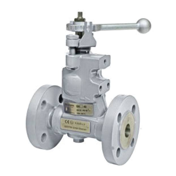
Continuous blowdown valve REAKTOMAT BA 46, BA 47 To open or close the continuous blowdown valve BA 46, BA 47 use the control lever and to set the required amount of boiler blowdown use the scale. The required amount of boiler blowdown can be calculated with the aid of a formula or read off on a nomogram. -
Page 10: Technical Data
The temperature/pressure ratings are indicated on the body or on the name plate. For more informa- tion see GESTRA technical documents such as data sheets and the Technical Information. According to EN 19 the name plate or the specification on the body indicate the type and design: Name/logo of the manufacturer ■... -
Page 11: Dimensions Ba 46, Ba 47
Technical Data - continued - Dimensions BA 46, BA 47 Fig. 2... -
Page 12: Dimensions Bae 46
Technical Data - continued - Dimensions BAE 46..., BAE 47... Fig. 3... -
Page 13: Dimensions Of Flanged Ends (Extract)
Technical Data - continued - Dimensions of flanged ends (extract) EN 1092-1 (2001) EN 1092-1 (2001) PN 40 PN 63 ∅ l [inch] ½ ¾ 1¼ 1½ 1½ [mm] [kg]*) 4.7/8.8 5.3/9.4 5.8/9.9 7.1/11.2 10.7/14.8 12.5/16.6 7.1/11.2 10.7/14.8 12.5/16.6 *) Weight BA 4... / Weight BAE 4... ASME B16.5 Class 150 ∅... -
Page 14: Dimensions Of Butt-Weld Ends (Extract)
Technical Data - continued - Dimensions of butt-weld ends (extract) DIN 3239-1, series 1 DIN 3239-1, series 2 DIN 2559-2 DIN 2559-2 [inch] ½ ¾ 1¼ 1½ 1½ [mm] 17.3 22.0 28.5 37.0 43.0 54.5 28.5 42.5 54.5 for pipe 21.3x2.0 26.9x2.3 33.7x2.6 42.4x2.6 48.3x2.6 60.3x2.9 33.7x2.6 48.3x2.9 60.3x2.9 [kg]*) 4.1/8.2 4.7/8.8... -
Page 15: Pressure /Temperature Ratings & End Connections
(max. pressure) [barg] (boiling point) [°C] Calculated in accordance with DIN EN 12516-2, * material according to AD 2000 BA 46, BAE 46, Flanged PN 40, EN 1092-1 (2013), A 105 (max. pressure) [barg] (boiling point) [°C] Calculated in accordance with DIN EN 12516-2 BA 47, BAE 47, Flanged PN 63 / PN 100, EN 1092-1 (2013), 1.0460*) -
Page 16: Materials
Technical Data - continued - Materials Type BA 4..., BAE 4... BA 4... ASME, BAE 4... ASME Designation DIN / EN ASTM Body 1.0460 A105 Nozzle stem 1.4021 A 276 Grade 420 Seat and stage sleeves 1.4104 430F Locking screw A2-70 A 192 CL 2B-BB Sealing plug... -
Page 17: Capacity Chart For Dn 15 To 32, Capacity Ranges At A Glance
Technical Data - continued - Capacity chart for DN 15 to 32, capacity ranges at a glance Differential pressure Position of control lever Fig. 4... -
Page 18: Capacity Chart For Dn 15 To 32 , Capacity Range Up To 310 Kg/H
Technical Data - continued - Capacity chart for DN 15 to 32 , capacity range up to 310 kg/h Differential pressure Position of control lever Fig. 5... -
Page 19: Capacity Chart For Dn 15 To 32 , Capacity Range Up To 1020 Kg/H
Technical Data - continued - Capacity chart for DN 15 to 32 , capacity range up to 1020 kg/h Differential pressure Position of control lever Fig. 6... -
Page 20: Capacity Chart For Dn 15 To 32 , Capacity Range Up To 2120 Kg/H
Technical Data - continued - Capacity chart for DN 15 to 32 , capacity range up to 2120 kg/h Differential pressure Position of control lever Fig. 7... -
Page 21: Capacity Chart For Dn 40 And 50, Capacity Ranges At A Glance
Technical Data - continued - Capacity chart for DN 40 and 50, capacity ranges at a glance Differential pressure Position of control lever Fig. 8... -
Page 22: Capacity Chart For Dn 40 And 50, Capacity Range Up To 1340 Kg/H
Technical Data - continued - Capacity chart for DN 40 and 50, capacity range up to 1340 kg/h Differential pressure Position of control lever Fig. 9... -
Page 23: Capacity Chart For Dn 40 And 50, Capacity Range Up To 4500 Kg/H
Technical Data - continued - Capacity chart for DN 40 and 50, capacity range up to 4500 kg/h Differential pressure Position of control lever Fig. 10... -
Page 24: Capacity Chart For Dn 40 And 50, Capacity Range Up To 6300 Kg/H
Technical Data - continued - Capacity chart for DN 40 and 50, capacity range up to 6300 kg/h Differential pressure Position of control lever Fig. 11... -
Page 25: Design
Design BA 46, BA 47 Fig. 12... -
Page 26: Bae 46
Design - continued - BAE 46..., BAE 47... Fig. 13... -
Page 27: Key
Design - continued - Stuffing box screw Scale plate Stuffing box gland Disk spring (3 pieces) Spring sleeve Packing with 4 wiper rings Guide sleeve Wear resisting sleeve Stage bushing Seat bushing Valve body Name plate ATEX marking GasketA 17 x 23 x 1.5 Sealing plug (connection for sample valve) Locking screw Gasket C6 x 10 x 1.5 (DN 15-32) C10 x 16 x 1.5 (DN 40,50) -
Page 28: Installation
Before commissioning read the technical documentation provided by the manufacturer of the actuator and store the document together with the installation manual "BA 46, BA 47, BAE 46..., BAE 47..." in a sheltered place. The continuous blowdown valve is delivered with a sampling valve (not installed). Attach... -
Page 29: Heat Treatment Of Welds
The internals of the continuous blowdown valve need not be removed before the heat treatment. Reposition control lever by 180 ° (if position of installation of BA 46 or BA 47 is unfavourable) If the position of installation is unfavourable (flow from right to left), it may be necessary to reposition the control lever by 180 °... -
Page 30: Electrical Connection
Electrical connection Danger Danger of bruising! During operation moving internals can pinch one's hands or fingers, causing severe injuries. Do not touch moving parts. The continuous blowdown valves BAE 46..., BAE 47... are remote-controlled and can open and close abruptly. The terminal strips of the actuator EF... -
Page 31: Commissioning Procedure
Always wear thermally insulated and heat resistant safety gloves when operating the valves. BA 46, BA 47, BAE 46..., BAE 47... Make sure that the flanged connections of the BA 46, BA 47, BAE 46..., BAE 47...are tightly bolted together and leakproof. The stuffing box gland must be re-tightened if leaks occur. -
Page 32: Operation
Always wear thermally insulated and heat resistant safety gloves when operating the valves. BA 46, BA 47, BAE 46..., BAE 47... Make sure that the flanged connections of the BA 46, BA 47, BAE 46..., BAE 47...are tightly bolted to- gether and leakproof. The stuffing box gland must be re-tightened if leaks occur. -
Page 33: Maintenance
BA 46, BA 47, BAE 46..., BAE 47... The continuous blowdown valves BA 46, BA 47, BAE 46... and BAE 47... do not require any special maintenance. Depending on the quality of the boiler water it might be necessary to service the valve every one or two years. -
Page 34: Bae 46
Maintenance - continued - BAE 46..., BAE 47... Changing packing and internals 01. Observe the danger note on page 5! 02. Cut off power supply to the actuator 03. Use hexagon screws and remove actuator and coupling 04. Unscrew the hexagon nut and detach the control lever with the aid of the pulling device. -
Page 35: Tightening Torques
Continuous blowdown valves DN 15-32: DN 40, 50 BA 46, BA 47, BAE 46..., BAE 47... BA 46, BA 47, BAE 46..., BAE 47... BA 46, BA 47, BAE 46..., BAE 47... BA 46, BA 47, BAE 46..., BAE 47... -
Page 36: Removing Internals
Maintenance - continued - Removing internals Fig. 14... -
Page 37: Mounting The Actuator
Retrofitting GESTRA continuous blowdown valves BA 46 and BA 47 can be retrofitted with an actuator EF... (BAE 46..., BAE 47...). Danger Danger of bruising! During operation moving internal parts can pinch one's hands or fingers, causing severe injuries. Do not touch moving parts. The continuous blowdown valves BAE 46..., BAE 47... -
Page 38: Spare Parts
Spare Parts Spare parts list Stock code # Stock code # Item Designation BA 46 BAE 46... BA 47 BAE 47... Packing & gasket kit, DN 15 to DN 32: 1 packing ring 15 x 23 x 8, 4 wiper rings,... -
Page 39: Parts For Retrofitting
Parts for retrofitting List of parts for retrofitting Stock code # Stock code # Item Designation BA 46 BAE 46... BA 47 BAE 47... 1 actuator EF 0.7, 230 V, 50/60 Hz, 1 mounting bracket, 336810 1 assembly set for coupling, 3 hexagon screws (for BAE 46-3) 1 actuator EF 0.7, 230 V, 50/60 Hz, 1 mounting bracket,... - Page 40 Agencies all over the world: www.gestra.com GESTRA AG Münchener Straße 77 28215 Bremen Germany Telefon +49 421 3503-0 Telefax +49 421 3503-393 E-mail info@de.gestra.com www.gestra.de 818609-03/06-2016cm (808708-05) · GESTRA AG · Bremen · Printed in Germany...
Need help?
Do you have a question about the BAE 46... and is the answer not in the manual?
Questions and answers