Table of Contents
Advertisement
Advertisement
Chapters
Table of Contents

Related Manuals for HYOSUNG Aquila GV250 Ej


Summarization of Contents
HOW TO USE THIS MANUAL
SYMBOL
Explains service symbols and their meanings for clarity.
ABBREVIATIONS USED IN THIS MANUAL
NOTE
Clarification on abbreviations used in the manual.
GENERAL INFORMATION
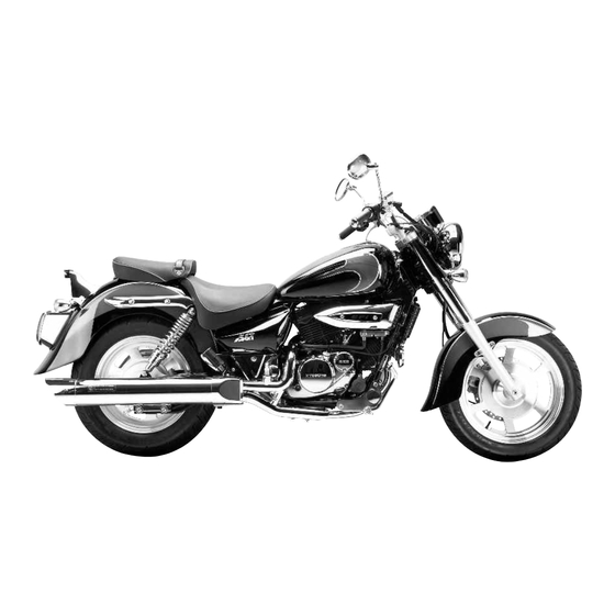
EXTERIOR PHOTOGRAPH
Shows a photograph of the vehicle's exterior.
EXTERIOR ILLUSTRATION GV250 EI
Illustrates exterior components with dimensions for GV250 EI.
EXTERIOR ILLUSTRATION GT250/P/REI
Illustrates exterior components with dimensions for GT250/P/REI.
FUNCTION OF EI SENSOR
Explains the function of the EI system's sensors.
SPECIFICATIONS
Lists key technical specifications for the vehicle models.
EI SYSTEM DIAGNOSIS
PRECAUTIONS IN SERVICING
Points to observe for EI system safety during servicing.
EI SYSTEM TECHNICAL FEATURES
Details the technical features and operation of the EI system.
SELF-DIAGNOSIS FUNCTION
Explains the self-diagnosis function modes and operation.
MALFUNCTION CODE AND DEFECTIVE CONDITION
Lists malfunction codes, detected items, and failure conditions for diagnosis.
EI SYSTEM TROUBLESHOOTING
CUSTOMER COMPLAINT ANALYSIS
Form for recording customer complaints and problem details.
PROBLEM SYMPTOMS
Lists common symptoms and possible causes for troubleshooting.
MOTORCYCLE / ENVIRONMENTAL CONDITION WHEN PROBLEM OCCURS
Environmental condition
Lists environmental factors like weather and road conditions.
Motorcycle condition
Lists operating conditions like engine and driving status.
SELF-DIAGNOSTIC PROCEDURES
PRECAUTIONS FOR ELECTRICAL CIRCUIT SERVICE
Important precautions before performing electrical circuit service.
SELF-DIAGNOSIS RESET PROCEDURE
LCD (DISPLAY) PANEL
Procedure to reset self-diagnosis via the LCD panel.
“FI” CHECK LAMP
Procedure to reset self-diagnosis using the "FI" check lamp.
SENSORS
PICK-UP COIL INSPECTION
Details inspection procedures for the pick-up coil.
PICK-UP COIL REMOVAL AND INSTALLATION
Instructions for removing and installing the pick-up coil.
IAP SENSOR INSPECTION
Details inspection procedures for the IAP sensor.
IAP SENSOR REMOVAL AND INSTALLATION
Instructions for removing and installing the IAP sensor.
TP SENSOR INSPECTION
Details inspection procedures for the TP sensor.
TP SENSOR REMOVAL AND INSTALLATION
Instructions for removing and installing the TP sensor.
ET SENSOR INSPECTION
Details inspection procedures for the ET sensor.
ET SENSOR REMOVAL AND INSTALLATION
Instructions for removing and installing the ET sensor.
IAT SENSOR INSPECTION
Details inspection procedures for the IAT sensor.
IAT SENSOR REMOVAL AND INSTALLATION
Instructions for removing and installing the IAT sensor.
RO SWITCH REMOVAL AND INSTALLATION
Instructions for removing and installing the RO switch.
FUEL SYSTEM AND THROTTLE BODY
FUEL SYSTEM
Details the fuel system components and related procedures.
THROTTLE BODY
Details the throttle body components and related procedures.
ELECTRICAL SYSTEM
LOCATION OF ELECTRICAL COMPONENTS
Shows the location of various electrical system components.
IGNITION SYSTEM
Details the ignition system components and operations.
CHARGING SYSTEM
Details the charging system components and operations.
STARTER SYSTEM AND SIDE STAND IGNITION INTERLOCK SYSTEM
Explains the starter and side stand interlock systems.
SERVICING INFORMATION
TROUBLESHOOTING
Provides a guide for diagnosing and resolving common issues.
SPECIAL TOOLS
Lists specialized tools required for servicing the vehicle.
TIGHTENING TORQUE
Specifies torque values for critical fasteners and parts.
SERVICE DATA
Lists electrical and sensor specifications for diagnostic purposes.
WIRING DIAGRAM
Provides electrical wiring diagrams for vehicle systems.
Need help?
Do you have a question about the Aquila GV250 Ej and is the answer not in the manual?
Questions and answers