Table of Contents
Advertisement
Quick Links
Download this manual
See also:
Training Manual
Advertisement
Table of Contents
Troubleshooting

Related Manuals for Mitsubishi FX3U-ENET


Summary of Contents for Mitsubishi FX3U-ENET
- Page 1 USER’S MANUAL -ENET...
-
Page 3: Safety Precautions
• SAFETY PRECAUTIONS • (Read these precautions before use.) Before installation, operation, maintenance or inspection of this product, thoroughly read through and understand this manual and all of the associated manuals. Also, take care to handle the module properly and safely. This manual classifies the safety precautions into two categories: “DANGER”... - Page 4 [Design Precautions] DANGER • Do not write any data in the "system area" of the buffer memory of the extension device. When writing a value to the buffer memory including "System Area," pay close attention not to change the system bit. If data is written to the "system area" or the "use prohibited" signal is output, there is a risk that the PLC system may malfunction.
- Page 5 [Wiring Instructions] DANGER • Before mounting or wiring the module, make sure to shut off all of the external power supply. Failure to do so may cause electric shocks or damage the module. • When turning on the power and operating after mounting or wiring the module, make sure to install the accessory terminal covers to the product.
- Page 6 This manual confers no industrial property rights or any rights of any other kind, nor does it confer any patent licenses. Mitsubishi Electric Corporation cannot be held responsible for any problems involving industrial property rights which may occur as a result of using the contents noted in this manual.
-
Page 7: Table Of Contents
CONTENTS SAFETY PRECAUTIONS..........................A- 1 CONTENTS..............................A- 5 About Manuals ...............................A- 9 Associated Manuals ............................A- 9 Applicable Standard ............................A-10 The Manual's Usage and Structure .......................A-11 About the Generic Terms and Abbreviations ....................A-14 1 OVERVIEW 1- 1 to 1- 9 1.1 Overview of the Ethernet Module ......................1- 1 1.2 Features of the Ethernet Module ...................... - Page 8 5 COMMUNICATION PROCEDURE 5- 1 to 5-49 5.1 Overview of the Communication Procedure ..................5- 1 5.2 Initial Processing ............................. 5- 3 5.2.1 Initial processing..........................5- 3 5.2.2 Initial settings............................ 5- 4 5.2.3 Re-initialization ..........................5-10 5.3 Router Relay Parameter ......................... 5-13 5.4 Confirming the Completion of the Initial Processing ................
- Page 9 8 COMMUNICATION USING MC PROTOCOL 8- 1 to 8- 6 8.1 Data Communication Function ....................... 8- 1 8.1.1 Accessing the PLC using MC protocol .................... 8- 1 8.1.2 How to Read the Control Procedures of the MC Protocol.............. 8- 3 8.1.3 Access Timing on the PLC Side ......................
- Page 10 11 TROUBLESHOOTING 11- 1 to 11-45 11.1 How to Check Errors Using LED Displays ..................11- 2 11.1.1 Checking error display ........................11- 2 11.1.2 How to turn off COM.ERR LED and to read/clear error information ........... 11- 4 11.2 How to Check an Error Through FX Configurator-EN (GX Developer) ..........11- 6 11.2.1 Buffer memory that can be monitored with the FX Configurator-EN (GX Developer) diagnostic function.........................
-
Page 11: About Manuals
The operation method of FX Configurator-EN. MODEL CODE: 09R919 Operation Manual How to obtain manuals For the necessary product manuals or documents, consult with the Mitsubishi Electric dealer. How to obtain FX Configurator-EN The parameter setting software, FX Configurator-EN is not supplied with this product. -
Page 12: Applicable Standard
• Power frequency magnetic field Notes for compliance to EMC regulation. It is necessary to install the (FX -ENET) in a shielded metal control panel. For more details please contact the local Mitsubishi Electric sales site. A - 10 A - 10... -
Page 13: The Manual's Usage And Structure
The Manual's Usage and Structure How to use this manual In this manual, explanations are given for each application of the Ethernet modules -ENET). Please use this manual using the following key items below as a reference. (1) Features and utility lists (a) Features and functions •... - Page 14 (e) Checking for connection errors with the external devices • Section 5.4.1 describes how to check for connection errors using the "PING" command. • Section 5.4.2 describes how to check for connection errors by performing the loopback test through MC protocol-based communication. (3) Connection between the Ethernet module and external devices (a) Communication procedures •...
- Page 15 (6) Checking for error occurrences and taking corrective actions (a) Error codes • Chapter 11 describes troubleshooting, how to check for errors, and the contents and reference manuals for error codes. (b) Error code storase area in the buffer memory of the Ethernet module •...
-
Page 16: About The Generic Terms And Abbreviations
About the Generic Terms and Abbreviations This manual uses the following generic terms and abbreviations to describe the Model FX -ENET Ethernet interface block. Description Generic Term/Abbreviation A machine-specific address that is also referred to as the MAC (Media Access Control Address). -
Page 17: Overview
1 OVERVIEW MELSEC-F 1 OVERVIEW This manual provides information on the specifications of the Ethernet interface block, -ENET (hereinafter called FX -ENET or the Ethernet module), as well as the procedures before starting operation, the control procedures and data communication method for communicating with external devices, maintenance, inspection, and troubleshooting. - Page 18 1 OVERVIEW MELSEC-F Collection and modification of PLC data (Communication using the MELSEC Communication Protocol (referred to below as the MC Protocol)) Transmission and reception of arbitrary data to/from external devices (Communication using fixed buffers) Data transmission/reception by e-mail (When using the e-mail function) By using the FX Configurator-EN (GX Developer) to set each parameter, the sequence programs for communication can be significantly simplified.
-
Page 19: Features Of The Ethernet Module
1 OVERVIEW MELSEC-F 1.2 Features of the Ethernet Module (1) Data communication using MC protocol (Details are explained in Chapter 8 and Chapter 9) Using MC protocol, the device data of the PLC can be read from/written to the host system. - Page 20 1 OVERVIEW MELSEC-F (3) Communication by e-mails (Details are explained in Chapter 10) Data can be sent to and received from an external device at a remote location using e-mail via an Internet line. Sending/receiving e-mail from the PLC The following data can be sent/received by e-mail.
- Page 21 1 OVERVIEW MELSEC-F (4) Connecting FX Configurator-EN (Details are explained in the Operating Manuals for FX Configurator-EN) Simplifying sequence programs using FX Configurator-EN (GX Developer) FX Configurator-EN (GX Developer) supports the parameter setting function to perform the Ethernet module initialization and the open processing with external devices.
- Page 22 1 OVERVIEW MELSEC-F Connecting multiple MELSOFT products (GX Developer, MX Component) This product can be connected with one or more MELSOFT product, via TCP/IP communication or UDP/IP communication. Connection via TCP/IP communication • If a MELSOFT product is to be connected with the FX configurator- EN (GX Developer) open settings, a maximum of four units can be connected with GX Developer.
-
Page 23: Software Configuration
1 OVERVIEW MELSEC-F 1.3 Software Configuration The Ethernet modules support the TCP/IP and UDP/IP protocols. OSI reference model corres- Personal computer/work-station(example) ponding to the PLC configuration (Layers) Main Unit User program From/To instruction Application layer Buffer memory System call Presentation layer... - Page 24 1 OVERVIEW MELSEC-F (2) UDP (User Datagram Protocol) This protocol may not guarantee data credibility or reliability in communication between a personal computer/work station and PLC that are connected via network. Thus, even if the data does not reach the target node, it will not be retransmitted.
- Page 25 1 OVERVIEW MELSEC-F 3) PSH (Push Bit) When this bit is ON (1), the host that has received this segment sends the data to the upper application with high priority. This bit is to be turned ON when the data should be sent to an external device as soon as possible.
-
Page 26: System Configurations
2 SYSTEM CONFIGURATIONS MELSEC-F 2 SYSTEM CONFIGURATIONS This section explains the system configurations that may be combined with the Ethernet modules. 2.1 Applicable Systems Ethernet modules can be used with the following systems: (1) Applicable PLC and number of modules that can be mounted The following table lists the PLC where the Ethernet module can be mounted and the number of modules that can be mounted. -
Page 27: Devices Required For Network Configuration
2 SYSTEM CONFIGURATIONS MELSEC-F 2.2 Devices Required for Network Configuration This section explains the devices that are required to configure a network. Network installation work requires sufficient safeguard; ask a network specialist for installation. When connecting FX -ENET to a network, either a 10BASE-T or 100BASE-TX can be used. - Page 28 2 SYSTEM CONFIGURATIONS MELSEC-F (2) Connection using the 10BASE-T * Up to 4 levels are allowed Twisted pair cable for cascade connection External device Ethernet module Use devices that satisfy the standards of IEEE802.3 and 10BASE-T. • Shielded twisted pair cable (STP cable), category 3 (4, 5) Straight cables can be used.
-
Page 29: Specifications
3 SPECIFICATIONS MELSEC-F 3 SPECIFICATIONS This section explains the Ethernet module performance specifications and transmission specifications. For more details on the general specifications, refer to the User's Manual for the PLC base module. 3.1 Performance Specifications The following explains the performance specifications of the Ethernet module. - Page 30 3 SPECIFICATIONS MELSEC-F NOTE The following explains each of the transmission specification items. [Connecting using the 10BASE-T] [Connecting using the 100BASE-TX] Maxmum Maxmum Maxmum 100m 100m Maxmum 5m 100m Up to Up to (2) levels are allowed for cascade 4 levels connection.
-
Page 31: Data Codes For Communication
3 SPECIFICATIONS MELSEC-F 3.2 Data Codes for Communication This section explains the data codes used in the communication between the Ethernet module and the external device or the PLC. (1) The data codes used while communicating are listed below. Ethernet module... - Page 32 3 SPECIFICATIONS MELSEC-F Ethernet module Data is sent and received in binary code. Ethernet module Binary code Commu- nication Binary code External data device storage ASCII code BIN/ASCII area conversion When communicating using ASCII code, 1-byte binary code data is automatically converted into 2-byte ASCII code data and then transmitted.
-
Page 33: Relationship Between The External Devices And Additional Functions For Each Communication Function
3 SPECIFICATIONS MELSEC-F 3.3 Relationship between the External Devices and Additional Functions for Each Communication Function This section explains which external devices data communication can be performed with and which additional functions can be used for each function. (1) Communicability with external devices using various functions The following table lists the communicability with external devices using various functions. -
Page 34: Ethernet Module Function List
3 SPECIFICATIONS MELSEC-F 3.4 Ethernet Module Function List This section shows a list of Ethernet module functions. (1) Basic functions of the Ethernet module The Ethernet module can perform the communications shown in the table below via TCP/IP or UDP/IP communication. -
Page 35: List Of Setting Items For Ethernet Modules
3 SPECIFICATIONS MELSEC-F 3.5 List of Setting Items for Ethernet Modules The following table lists the parameter setting items that are set using Ethernet Module. Function and parameter setting Refer-ence Parameter setting item Description of setting requirement ( section Fixed... -
Page 36: List Of Applications And Assignments Of The Buffer Memory
3 SPECIFICATIONS MELSEC-F 3.6 List of Applications and Assignments of the Buffer Memory Data transmission/reception between Ethernet Module and PLC is performed via the Ethernet Module buffer memory (hereinafter called BFM). Reading/writing data in the buffer memory from the PLC must be performed by the FROM/TO instructions (instructions that can access BFM). - Page 37 3 SPECIFICATIONS MELSEC-F (2) Assignments of the buffer memory A buffer memory consists of 16 bits per address. <Bit configuration diagram> The following shows the buffer memory addresses. Initial processing parameter (BFM #0 to 31) BFM number Initial value Reference...
- Page 38 3 SPECIFICATIONS MELSEC-F (Continued from the previous page) BFM number Initial value Flash Reference Attribute Application Name Decimal Decimal ROM save section (Hexadecimal) (Hexadecimal) Communication condition setting (Operational Settings) area • Communication data code setting (b1) 0: Communication in binary code 1: Communication in ASCII code •...
- Page 39 3 SPECIFICATIONS MELSEC-F (Continued from the previous page) BFM number Initial value Flash ROM Reference Attribute Application Name Decimal Decimal save section (Hexadecimal) (Hexadecimal) Stores Ethernet module status b0: INIT 1: Initial processing normally completed 0: — b1: System bit...
- Page 40 3 SPECIFICATIONS MELSEC-F Communication parameter setting area (BFM #32 to 102) BFM number Initial value Flash Reference Attribute Application Name Decimal Decimal section (Hexadecimal) save (Hexadecimal) Connection No. 1 • Usage of fixed buffer (b0) 0: For sending or fixed buffer communication is...
- Page 41 3 SPECIFICATIONS MELSEC-F (Continued from the previous page) BFM number Initial value Flash Reference Attribute Application Name Decimal Decimal section (Hexadecimal) save (Hexadecimal) Local station Port No. Section 5.5 41 to 42 Destination IP address Section 5.5 Connection (29 to 2A No.
- Page 42 3 SPECIFICATIONS MELSEC-F Communication status storage area (BFM #103 to 226) BFM number Initial value Flash ROM Reference Attribute Application Name Decimal Decimal save section (Hexadecimal) (Hexadecimal) 103 to 104 System area to 68 Initial error code Section 11.4 106 to 107...
- Page 43 3 SPECIFICATIONS MELSEC-F (Continued from the previous page) BFM number Initial value Flash ROM Referenc Attribute Application Name Decimal Decimal save e section (Hexadecimal) (Hexadecimal) Operation mode settings 0: Online Communication 1: Offline status storage 2: Self loopback test area...
- Page 44 3 SPECIFICATIONS MELSEC-F Error log partition area (BFM #227 to 511) BFM number Initial value Flash ROM Reference Attribute Application Name Decimal Decimal save section (Hexadecimal) (Hexadecimal) Number of error occurrences Section 11.4 Error log write pointer Error code/end code...
- Page 45 3 SPECIFICATIONS MELSEC-F (Continued from the previous page) BFM number Initial value Flash ROM Reference Attribute Application Name Decimal Decimal save section (Hexadecimal) (Hexadecimal) 376 to 377 Received IP packet count (178 to 179 378 to 379 Received IP packet count discarded Section 11.3...
- Page 46 3 SPECIFICATIONS MELSEC-F Router relay parameter setting area (BFM #512 to 1599) BFM number Initial value Flash ROM Reference Attribute Application Name Decimal Decimal save section (Hexadecimal) (Hexadecimal) 512 to 513 Sub-net mask (200 to 201 Router relay Section 5.3...
- Page 47 3 SPECIFICATIONS MELSEC-F (Continued from the previous page) BFM number Initial value Flash ROM Reference Attribute Application Name Decimal Decimal save section (Hexadecimal) (Hexadecimal) Connection No.1 Open/Close command • Write value 0001H: Open command 8000H: Close command • Read value...
- Page 48 3 SPECIFICATIONS MELSEC-F (Continued from the previous page) BFM number Initial value Flash ROM Reference Attribute Application Name Decimal Decimal save section (Hexadecimal) (Hexadecimal) When sending request or reception complete confirmation signal of connection No.1 • For sending 1) Write value...
- Page 49 3 SPECIFICATIONS MELSEC-F (Continues on the next page) BFM number Initial value Flash ROM Reference Attribute Application Name Decimal Decimal save section (Hexadecimal) (Hexadecimal) 1611 When sending request or reception complete (Same as connection No.1) (652 confirmation signal of connection No.2...
- Page 50 3 SPECIFICATIONS MELSEC-F Mail send parameter settings (BFM #9856 to 14499) Reference Initial value BFM number Flash ROM section Attribute Application Name Decimal save Decimal (Hexadecimal) (Hexadecimal) 9856 to 9887 Local station mail address (Maximum of 64 words) "\0" Chapter 10...
- Page 51 3 SPECIFICATIONS MELSEC-F (Continued from the previous page) Reference Initial value BFM number Flash ROM section Attribute Application Name Decimal save Decimal (Hexadecimal) (Hexadecimal) • Write value Mail sending instruction (0001H) 10333 Mail sending Chapter 10 • Read value (0000...
- Page 52 3 SPECIFICATIONS MELSEC-F Mail receive parameter settings (BFM #14500 to 20479) BFM number Initial value Flash ROM Reference Attribute Application Name Decimal Decimal save section (Hexadecimal) (Hexadecimal) • Write value Receive mail instruction (0001H) • Read value 14500 Mail receiving...
- Page 53 3 SPECIFICATIONS MELSEC-F Connection status storage area (BFM #20480 to 22639) BFM number Initial value Flash ROM Reference Attribute Application Name Decimal Decimal save section (Hexadecimal) (Hexadecimal) Open complete signal 0: Open incomplete 1: Open completed • Connection No. 1 (b0) 20480 •...
- Page 54 3 SPECIFICATIONS MELSEC-F E-mail status storage area (BFM #22640 to 31999) BFM number Initial value Flash ROM Reference Attribute Application Name Decimal Decimal save section (Hexadecimal) (Hexadecimal) 22640 Number of mails remaining on the server Section 11.4 (5870 22641 to 22642...
- Page 55 3 SPECIFICATIONS MELSEC-F (Continued from the previous page) NFM number Initial value Flash ROM Reference Attribute Application Name Decimal Decimal save section (Hexadecimal) (Hexadecimal) 23353 to 23354 System area (5B39 to 5B3A 23355 Number of mails normally completed (5B3B 23356...
- Page 56 3 SPECIFICATIONS MELSEC-F (Continued from the previous page) BFM numebr Initial value Flash ROM Reference Attribute Application Name Decimal Decimal save section (Hexadecimal)) (Hexadecimal) Designates the error information to be cleared 0000H : Clears initial error code (BFM#105) 0001H to 0008H : Clears the open error code of connection 1 to 8 (BFM#124, 134, 144, 154, 164, 174, 184, 194).
-
Page 57: Settings And Procedures Prior To Operation
4 SETTINGS AND PROCEDURES PRIOR TO OPERATION MELSEC-F 4 SETTINGS AND PROCEDURES PRIOR TO OPERATION This chapter explains the settings and procedures required prior to operating the Ethernet module in a system. 4.1 Loading and Installation This section explains precautions for Ethernet module handling from unpacking to installation, as well as the installation environment common to all modules. - Page 58 4 SETTINGS AND PROCEDURES PRIOR TO OPERATION MELSEC-F • Be careful not to let any foreign matter such as wire chips get inside the module. CAUTION They may cause fire, as well as breakdowns and malfunctions of the module. • Never disassemble or modify the module.
-
Page 59: Installation Environment
4 SETTINGS AND PROCEDURES PRIOR TO OPERATION MELSEC-F 4.1.2 Installation environment This section explains the installation environment for the PLC. When installing the PLC, the following environments must be avoided: • Locations where the ambient temperature exceeds the range of 0 to 55 °C. -
Page 60: Settings And Procedures Prior To Starting The Operation
4 SETTINGS AND PROCEDURES PRIOR TO OPERATION MELSEC-F 4.2 Settings and Procedures Prior to Starting the Operation The following shows a flow of the procedure that is required prior to operating: Procedures prior to operation Connect the Ethernet module to the base module and wire the 24VDC power supply. - Page 61 4 SETTINGS AND PROCEDURES PRIOR TO OPERATION MELSEC-F Important Do not write any data in the "System area" of the intelligent function module buffer memory. When status control (such as remote RUN/STOP) from a external device is used for the PLC, the user should select "Always wait for OPEN" beforehand using the setting parameters.
-
Page 62: Components Of The Ethernet Module
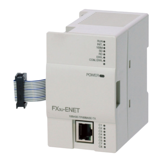
4 SETTINGS AND PROCEDURES PRIOR TO OPERATION MELSEC-F 4.3 Components of the Ethernet Module This section shows the components of the Ethernet module. View with the cover removed Name Description LED display Refer to the contents of the LED displays (1). - Page 63 4 SETTINGS AND PROCEDURES PRIOR TO OPERATION MELSEC-F (1) LED display contents LED name Display description When the LED is on When the LED is off Normal Abnormal Normal operation display (when FROM/TO instruction can (when WDT is in operation)
-
Page 64: Connecting To The Network
4 SETTINGS AND PROCEDURES PRIOR TO OPERATION MELSEC-F 4.4 Connecting to the Network The following explains how to connect the Ethernet module to the 100BASE-TX/ 10BASE-T networks. Some precautions that should be observed while connecting the Ethernet module are also shown below. Pay close attention to safety and use the Ethernet module properly. -
Page 65: Connecting To The 10Base-T/100Base-Tx Network
4 SETTINGS AND PROCEDURES PRIOR TO OPERATION MELSEC-F 4.4.1 Connecting to the 10BASE-T/100BASE-TX network This section explains how to connect the Ethernet module to the 10BASE-T, 100BASE-TX network. The following shows the connection diagram for the twisted paid cable. RJ45 type modular... -
Page 66: Setting Ethernet Parameters
4 SETTINGS AND PROCEDURES PRIOR TO OPERATION MELSEC-F 4.5 Setting Ethernet Parameters Setting the Ethernet module as a network module. The settings found must always be set in order to use the Ethernet module. (1) "Operational settings" (Details are explained in Section 4.6) This screen is for setting common items for when other modules use the Ethernet module. -
Page 67: Operational Settings
4 SETTINGS AND PROCEDURES PRIOR TO OPERATION MELSEC-F 4.6 Operational Settings This section explains how to set the operations parameters. BFM number [Decimal] Setting name Setting description Setting range/selection (bit number) OFF : Binary code Communication data code 24 (b1) Select the communication data code. - Page 68 4 SETTINGS AND PROCEDURES PRIOR TO OPERATION MELSEC-F (2) TCP Existence confirmation setting (BFM #24 b4) Select the existence check method for TCP communication. For the existence check function, refer to Section 5.2.2. Name of setting Description of setting Use the KeepAlive Checks connection status with KeepAlive.
- Page 69 4 SETTINGS AND PROCEDURES PRIOR TO OPERATION MELSEC-F (4) Initial Timing (BFM#24 b8) Select the timing to open connections for which TCP-Passive open or UDP open are selected with the "Open settings" parameter ( 1) . 1 For more details on the open settings, see Section 5.5 "Open Settings".
- Page 70 4 SETTINGS AND PROCEDURES PRIOR TO OPERATION MELSEC-F (5) IP Address settings – IP address (BFM #0 to 1) Set the IP address of the local station according to the specified input format (decimal or hexadecimal). It should be set so that the local station Ethernet module and the communicating external device have the same class and sub-net address (two words).
-
Page 71: Self-Diagnostic Tests
4 SETTINGS AND PROCEDURES PRIOR TO OPERATION MELSEC-F 4.7 Self-Diagnostic Tests This section explains the self-diagnostic tests for checking the hardware and transmission and reception function of the Ethernet module. 4.7.1 Self loopback test The following explains the self loopback test that is used to check the hardware including the Ethernet module’s transmission and reception circuit. -
Page 72: Hardware Test (H/W Test)
4 SETTINGS AND PROCEDURES PRIOR TO OPERATION MELSEC-F 4.7.2 Hardware test (H/W Test) This section explains the RAM and ROM tests for the Ethernet module. The procedure for the hardware test is as shown in the table below. The test results are judged from the LED displays on the front of the Ethernet module. -
Page 73: Maintenance And Inspection
4 SETTINGS AND PROCEDURES PRIOR TO OPERATION MELSEC-F 4.8 Maintenance and Inspection This section explains the maintenance and inspection as well as the installing and uninstalling of the Ethernet module. 4.8.1 Maintenance and inspection The Ethernet module does not need to be inspected for anything particular other than checking whether or not the connections of cables and the terminal screws are loose. -
Page 74: Installing And Uninstalling The Module
4 SETTINGS AND PROCEDURES PRIOR TO OPERATION MELSEC-F 4.8.2 Installing and uninstalling the module Before installing or uninstalling the Ethernet module, make sure to read Section 4.1, "Handling Precautions" thoroughly, ensure the safety of the installation, and handle the module properly according to the instructions. -
Page 75: Communication Procedure
5 COMMUNICATION PROCEDURE MELSEC-F 5 COMMUNICATION PROCEDURE This chapter gives an overview of the communication procedure using the Ethernet module, as well as the required initial processing of the Ethernet prior to data communication and the open processing for communication with an external device. - Page 76 5 COMMUNICATION PROCEDURE MELSEC-F NOTE Each of the following two types of communication can be performed with an external device opened by the user. • Communication using MC protocol • Sending/receiving in fixed buffer communication (procedure exists) When receiving communication request data from an external device...
-
Page 77: Initial Processing
5 COMMUNICATION PROCEDURE MELSEC-F 5.2 Initial Processing This section explains the initial processing of the Ethernet module. 5.2.1 Initial processing The initial processing enables data communication with an external device by setting the parameters required for data communication via the Ethernet module. -
Page 78: Initial Settings
5 COMMUNICATION PROCEDURE MELSEC-F 5.2.2 Initial settings This section explains the initial settings. BFM number Setting item name Description of setting Setting range/options (Decimal) TCP ULP timer Set the time of packet existence at TCP data transmission. 2 to 32767 TCP zero window timer Set the interval for checking the reception enabled status. - Page 79 5 COMMUNICATION PROCEDURE MELSEC-F (1) Timer setting – TCP ULP timer (BFM#4) This item sets the time of packet existence during TCP data sending. This timer is passed through the parameter when TCP opens or data is sent. Set the value in the range from 2 to 32767.
- Page 80 5 COMMUNICATION PROCEDURE MELSEC-F (5) Timer setting - IP assembly timer (BFM#8) Communication data may be divided on the IP level due to the buffer restriction at the sending or receiving station. Set the value in the range from 1 to 32766.
- Page 81 • timer value timer value Furthermore, when connecting a line using Mitsubishi products, you should make sure that both nodes have the same settings. (2) Set the value of each timer on the external device side such way that the following relations are met.
- Page 82 5 COMMUNICATION PROCEDURE MELSEC-F (3) When communication errors occur, the setting value should be changed to increase the number of retries. The number of retries is obtained by using the following equation: (In case of the default values, 2 = (60/20) - 1)
- Page 83 5 COMMUNICATION PROCEDURE MELSEC-F Checking by KeepAlive This method is used for a connection opened via the TCP/IP protocol. The Ethernet module performs an existence check by sending an existence check ACK message to a remote device with which communication has not been performed for a certain period of time and waiting to see whether or not a response is received.
-
Page 84: Re-Initialization
5 COMMUNICATION PROCEDURE MELSEC-F 5.2.3 Re-initialization Re-initialization is performed in order to place the Ethernet module into its startup status without actually restarting the PLC. Re-initialization of the Ethernet module can be performed in a sequence program. The purposes of and how to program the re-initialization of the Ethernet module are explained below. - Page 85 5 COMMUNICATION PROCEDURE MELSEC-F (2) Programming and timing for re-initialization The programming and timing for re-initialization is shown below: <<Re-initialization>> Instruction Re-initialization request self-holding Upon completion of Ethernet H0001 MOVP H0001 module initial processing, G1600 re-initialization is performed Self-holding cancel...
- Page 86 5 COMMUNICATION PROCEDURE MELSEC-F (3) Operation for re-initialization Operation for re-initialization differs as follows, depending on the value written to BFM#1600. Operation Written value COM. ERR LED Re-reading flash ROM 0001H Not re-read Turns off 0002H Re-read 0005H Not re-read...
-
Page 87: Router Relay Parameter
5 COMMUNICATION PROCEDURE MELSEC-F 5.3 Router Relay Parameter This section explains the router relay parameter. Setting item name BFM number (Decimal) Description of setting Setting range/options 00 : Use Router relay function Select whether the router relay function is not used or is used. - Page 88 5 COMMUNICATION PROCEDURE MELSEC-F (2) Subnet mask pattern (BFM#512, 513) Set the subnet mask. (Setting range: C0000000 to FFFFFFF) Consult the network administrator for the setting. When not using the subnet mask, set any of the following table values according to the class.
- Page 89 5 COMMUNICATION PROCEDURE MELSEC-F (3) Router IP address (BFM#514, 515) Set the IP address of the router to be used when FX -ENET communicates with the target device on another Ethernet network (refer to (4) below). Set the value that satisfies the following conditions.
- Page 90 5 COMMUNICATION PROCEDURE MELSEC-F (Setting example 1) When the network addresses of the local station Ethernet module and target device differ Network address Local station Ethernet module IP address (Class B) 1 0 0 0 0 0 0 1 0 0 0 0 0 1 0 1...
- Page 91 5 COMMUNICATION PROCEDURE MELSEC-F (Setting example 3) When the network addresses of the local station Ethernet module and target device are the same Network address Local station Ethernet module 1 0 0 0 0 0 0 1 0 0 0 0 0 1 0 1...
-
Page 92: Confirming The Completion Of The Initial Processing
5 COMMUNICATION PROCEDURE MELSEC-F 5.4 Confirming the Completion of the Initial Processing The initial processing for the Ethernet module completes by selecting re-initialization, then turning the power ON again, or re-initializing via buffer memory operations after parameters are written to the Ethernet module. -
Page 93: Ping Command (Personal Computer Ethernet Module)
5 COMMUNICATION PROCEDURE MELSEC-F 5.4.1 PING command (Personal computer Ethernet module) The following example illustrates how to confirm the completion of the initial processing by issuing the PING command to the local station’s Ethernet module from an external device connected on the same Ethernet network. (In the example, the confirmation is made between devices whose IP address class and sub-net address are identical.) -
Page 94: Loop Back Test (Communication Using Mc Protocol)
5 COMMUNICATION PROCEDURE MELSEC-F 5.4.2 Loop back test (Communication using MC protocol) The loop back test can be performed with communication using MC protocol in order to check the completion status of the initial processing for the target Ethernet module. -
Page 95: Open Settings
5 COMMUNICATION PROCEDURE MELSEC-F 5.5 Open Settings This section explains the open setting. A sequence program can perform open processing (establishing connection) with up to a maximum of 8 external device stations Once a connection is established with an external device, it is possible to communicate using MC protocol, fixed buffer communication. - Page 96 5 COMMUNICATION PROCEDURE MELSEC-F (1) Protocol (connection numbers 1 to 8; BFM#32 to 39 b8) Select the protocol for each connection. Name of setting Description of setting Communicate using TCP/IP. Communicate using UDP/IP. For protocols (TCP/UDP), see 1.3, "Software Configuration".
- Page 97 5 COMMUNICATION PROCEDURE MELSEC-F (3) Fixed buffer (connection numbers 1 to 8; BFM#32 to 39 b0) Here it is selected whether the fixed buffer corresponding to each applicable connection number will be used for sending or receiving when communicating using the fixed buffers.
- Page 98 5 COMMUNICATION PROCEDURE MELSEC-F (5) Pairing open (connection numbers 1 to 8; BFM#32 to 39 b7) Select whether or not the Ethernet module's receiving and sending connections are made into one pair and connected to one port of an external device when using fixed buffer communication (either of the procedure exist or no procedure can be designated).
- Page 99 5 COMMUNICATION PROCEDURE MELSEC-F (7) Local station Port No. (connection numbers 1 to 8; BFM#40, 47, 54, 61, 68, 75, 82, 89) In this item the port number of each connection for the Ethernet module is set in Decimal. The setting values are designated in the range from 1025 to 5548 and from 5552 to 65534.
- Page 100 5 COMMUNICATION PROCEDURE MELSEC-F (9) Destination Port No. (connection numbers 1 to 8; BFM#43, 50, 57, 64, 71, 78, 85, 92) Set the port numbers of the external devices for each connection in decimal. The port numbers of the external devices are set in the range from 1025 to 65535.
- Page 101 5 COMMUNICATION PROCEDURE MELSEC-F POINT Set parameters according to the open method to be used for open connection. Communication system open system Active Passive ARP function of ARP function of external device external device Un-passive Full-passive Parameter Local station Port...
-
Page 102: Open Processing/Close Processing Of The Connection
5 COMMUNICATION PROCEDURE MELSEC-F 5.6 Open Processing/Close Processing of the Connection This section explains the open processing/close processing using sequence programs. (1) Open processing The purpose of the open processing is to establish a connection with an external device in order to perform the following forms of data communication. - Page 103 5 COMMUNICATION PROCEDURE MELSEC-F (2) Close processing The purpose of the close processing is to disconnect (cancel) the connection with the external device established by open processing mentioned previously. The close processing is used when terminating a connection with an external device, changing an external device of a connection, changing communication conditions, etc.
-
Page 104: Active Open Processing/Close Processing
5 COMMUNICATION PROCEDURE MELSEC-F 5.6.1 Active open processing/close processing This section explains the procedure for opening and closing a connection with an external device from the Ethernet module. M8000 [MOV K4M110 Status Status read Initial Initial completion completion signal status... - Page 105 5 COMMUNICATION PROCEDURE MELSEC-F 1) Parameter update Power-on completed Open status Hub connected Open allowed status Closed status Initial normal completion BFM#27=0001H Hub connected signal BFM #28b7 OPEN status CLOSE OPEN CLOSE CLOSE OPEN CLOSE OPEN/ CLOSE instruction 0005H instruction...
- Page 106 5 COMMUNICATION PROCEDURE MELSEC-F POINT This example uses connection number 1 for explanation. Use the corresponding BFM No. and bits for other connection numbers. 1 Processing when the open processing is abnormally completed (TCP) When opening from the Ethernet module under a normal situation, if the Ethernet module sends a SYN, the external device returns an ACK and a SYN.
- Page 107 5 COMMUNICATION PROCEDURE MELSEC-F The open request signal turns off by writing "8000 " to the BFM#1602. The Ethernet module executes the close processing. The Ethernet module sends a FIN request to the external device. The external device sends back FIN and ACK messages in reply to the FIN request sent by the Ethernet module.
- Page 108 5 COMMUNICATION PROCEDURE MELSEC-F Program example This example explains a program for open processing/close processing when Active open is selected in the Open system setting. (1) Execution environment for the program example The Ethernet module is connected to the second special module.
- Page 109 5 COMMUNICATION PROCEDURE MELSEC-F (2) Outline of the program example After each parameter is set in FX Configurator-EN (GX Developer) or the sequence program and written to the Ethernet module, re-initialize or power ON the module again and confirm the completion of the initial processing via buffer memory operations.
-
Page 110: Passive Open Processing/Close Processing
5 COMMUNICATION PROCEDURE MELSEC-F 5.6.2 Passive open processing/close processing This section explains the procedure for opening and closing a connection with the Ethernet module via an external device. The operations of Passive open processing/close processing differ depending on whether "Always wait for OPEN" or "Do not wait for OPEN" is selected, as shown in this section. - Page 111 5 COMMUNICATION PROCEDURE MELSEC-F After the parameters are sent, the normal completion of the Ethernet module initial processing is confirmed (Initial normal completion signal (BFM#27 "0001 ") After the initial processing is normally completed, the connection is placed in the open allowed status and the Ethernet module waits for an open request from the external device.
- Page 112 5 COMMUNICATION PROCEDURE MELSEC-F (2) When "Do not wait for OPEN" is selected in the operational setting When initial timing settings of operational settings are at [Do not wait for OPEN (communication impossible at STOP time)], the (BFM #24 b8: OFF) open processing/close processing is performed as explained below.
- Page 113 5 COMMUNICATION PROCEDURE MELSEC-F Parameter communication Power-on completed Open status Open allowed status (closed) (*1) (Active open acknowledge enabled) Closed status Initial normal completion BFM#27="0001H" 0001H 8000H 0001H OPEN/ CLOSE operation TO BFM#1602 OPEN/ CLOSE status 0000H 0003H 0005H 0009H...
- Page 114 5 COMMUNICATION PROCEDURE MELSEC-F 1 If an open request (SYN) received after the normal completion of an initial processing and before the Ethernet module is placed in the open acknowledge enabled status, an error is generated, and the Ethernet module sends a connection forced close (RST).
- Page 115 5 COMMUNICATION PROCEDURE MELSEC-F Program example This example explains a program for open processing/close processing when Unpassive open is selected in the open system setting. (1) Execution environment for the program example The Ethernet module is connected to the second special module.
- Page 116 5 COMMUNICATION PROCEDURE MELSEC-F (2) Outline of the program example The open processing for connection No. 1 of the Ethernet module is performed. After the completion of the open processing, connection No. 1 waits for the open request from the external device.
-
Page 117: Udp/Ip Open Processing/Close Processing
5 COMMUNICATION PROCEDURE MELSEC-F 5.6.3 UDP/IP open processing/close processing The following explains the UDP/IP open processing. The operations of the open processing/close processing in UDP/IP differ depending on whether “Always wait for OPEN” or “Do not wait for OPEN” is selected in the initial timing settings (BFM #24 b8) from operational settings. - Page 118 5 COMMUNICATION PROCEDURE MELSEC-F <<Open processing for connection No.1>> M8000 [MOV K4M110 ] Status Status read value Initial Initial completion completion signal status X000 [MOVP G1602 OPEN Open Initial instruction/ request completion status status [MOV G1602 D100 OPEN instruction/ status...
- Page 119 5 COMMUNICATION PROCEDURE MELSEC-F Parameter Power-on update completed Open status Closed status Initial normal completion BFM#27=001 OPEN/CLOSE instruction and status BFM#1602 W0001H R0005H 0000H 0009H 0000H 8000H Open completion signal (BFM#20480) Internal Internal processing processing After communicating the parameter settings, confirm the normal completion of the Ethernet module initial processing.
-
Page 120: Pairing Open
5 COMMUNICATION PROCEDURE MELSEC-F 5.7 Pairing Open The following explains communication using the paring open method via the Ethernet module. 5.7.1 Pairing open Pairing open is an opening method for establishing a connection in which the local station and the external device use a single port for each, by pairing the receiving and sending connections through fixed buffer communication (both the procedure exists and no procedure are allowed) of the Ethernet module. -
Page 121: Example Of Pairing Open Settings
5 COMMUNICATION PROCEDURE MELSEC-F 5.7.2 Example of pairing open settings This section explains the settings in order to communicate in the pairing open method by giving an example. • Connection No. 1 and 2 are used. (When connection No. 1 is specified at pairing open settings, connection No. 2 is automatically used as pairing. - Page 122 5 COMMUNICATION PROCEDURE MELSEC-F (7) Local station Port No. (BFM#40, 47) Set this for the receiving connection for receiving only. (Setting is not required for the sending connection.) Set the port number upon consulting a network administrator. (8) Destination IP address (BFM#41 to 42, 48 to 49) If the setting is not required •...
-
Page 123: Hub Connection Status Monitor Function
5 COMMUNICATION PROCEDURE MELSEC-F 5. 8 Hub Connection Status Monitor Function The current connection status of the Ethernet module and hub, the transmission speed, and the number of times the Ethernet module detected disconnection can be checked at the following buffer memory addresses. -
Page 124: Fixed Buffer Communication (With The Procedure Exist Control Method)
6 FIXED BUFFER COMMUNICATION (WITH THE PROCEDURE EXIST CONTROL METHOD) MELSEC-F 6 FIXED BUFFER COMMUNICATION (WITH THE PROCEDURE EXIST CONTROL METHOD) This chapter explains how the PLC and external device communicate in a 1:1 mode using the fixed buffers (with the procedure exist control method) of the Ethernet module. - Page 125 6 FIXED BUFFER COMMUNICATION (WITH THE PROCEDURE EXIST CONTROL METHOD) MELSEC-F POINT In communication where the procedure exist control method is selected, the data can be communicated by the following methods after the open processing is completed. • Fixed buffer communication with the procedure exist control method (sending or receiving) •...
-
Page 126: Sending Control Method
6 FIXED BUFFER COMMUNICATION (WITH THE PROCEDURE EXIST CONTROL METHOD) MELSEC-F 6.2 Sending Control Method This section explains the control method when data is sent from the Ethernet module to an external device using the fixed buffer No. 1 and the area corresponding to connection No. - Page 127 6 FIXED BUFFER COMMUNICATION (WITH THE PROCEDURE EXIST CONTROL METHOD) MELSEC-F Confirm the normal completion of the initial processing. Confirm the normal completion of the open processing of connection No. 1 Write the send data word count and the send data in the fixed buffer data area (communication address setting area: BFM#1664 to 2687) by TO instruction.
-
Page 128: Receiving Control Method
6 FIXED BUFFER COMMUNICATION (WITH THE PROCEDURE EXIST CONTROL METHOD) MELSEC-F 6.3 Receiving Control Method This section explains the control method when the Ethernet module receives data from an external device. 6.3.1 Receive processing with the main program This section explains the receiving process to be performed with the main program, using an example in which the fixed buffer No. - Page 129 6 FIXED BUFFER COMMUNICATION (WITH THE PROCEDURE EXIST CONTROL METHOD) MELSEC-F Confirm the normal completion of the open processing of connection No. 2. Upon receiving data from the designated external device (set in the open processing), the Ethernet module processes the following.
-
Page 130: Data Format
6 FIXED BUFFER COMMUNICATION (WITH THE PROCEDURE EXIST CONTROL METHOD) MELSEC-F 6.4 Data Format When communicating between the Ethernet module and an external device, the data format explained below is used. The communication data consists of a "header" and "application data" as follows:... -
Page 131: Application Data
6 FIXED BUFFER COMMUNICATION (WITH THE PROCEDURE EXIST CONTROL METHOD) MELSEC-F 6.4.2 Application data As shown below, the data code in the application data can be expressed in either binary or ASCII code. Switching between binary code and ASCII code is performed via the communication data code setting (BFM #24 b1 OFF: binary, ON: ASCII code). - Page 132 6 FIXED BUFFER COMMUNICATION (WITH THE PROCEDURE EXIST CONTROL METHOD) MELSEC-F (2) Subheader The format of the subheader is as shown below. The user does not need to set the subheader when using the Ethernet module since the Ethernet module adds and deletes it.
- Page 133 6 FIXED BUFFER COMMUNICATION (WITH THE PROCEDURE EXIST CONTROL METHOD) MELSEC-F (3) Data length setting This value indicates the data size of the text (command) section. POINT The data length can be designated in the following range: • Communication using binary code: Maximum of 1017 words •...
- Page 134 6 FIXED BUFFER COMMUNICATION (WITH THE PROCEDURE EXIST CONTROL METHOD) MELSEC-F (b) Communication using ASCII code Command format Maximum of 1016 words (H) to (L) (H) to (L) (H) to (L) (H) to (L) Subheader ASCII-BIN conversion Data designation/ storage device...
-
Page 135: Programming
6 FIXED BUFFER COMMUNICATION (WITH THE PROCEDURE EXIST CONTROL METHOD) MELSEC-F 6.5 Programming This section explains the programming method when the Ethernet module communicates with an external device using fixed buffers and the procedure exist control method. 6.5.1 Precautions when creating programs In order to communicate using the fixed buffer, the initial processing and the connection open processing must be completed. -
Page 136: Fixed Buffer Communication Program Example (With The Procedure Exist Control Method)
6 FIXED BUFFER COMMUNICATION (WITH THE PROCEDURE EXIST CONTROL METHOD) MELSEC-F 6.5.2 Fixed buffer communication program example (with the procedure exist control method) This section explains the programming method in order to communicate data (procedure exist control method) with an external device using the fixed buffers. -
Page 137: Control Method
6 FIXED BUFFER COMMUNICATION (WITH THE PROCEDURE EXIST CONTROL METHOD) MELSEC-F Fixed buffer No. 2 receive data : Stored in D700 to D703 Fixed buffer No. 1 receive instruction complete device : M500 10) Fixed buffer No. 1 receive instruction abnormal complete device : M501 11) Fixed buffer No. - Page 138 6 FIXED BUFFER COMMUNICATION (WITH THE PROCEDURE EXIST CONTROL METHOD) MELSEC-F (2) Outline of the program example (a) Send program (Ethernet module-1st station side) After setting each parameter with FX Configurator-EN (GX Developer) or a sequence program and writing to the Ethernet module, select re- initial, power ON the module again, or confirm that the initial processing is completed via buffer memory operations.
- Page 139 6 FIXED BUFFER COMMUNICATION (WITH THE PROCEDURE EXIST CONTROL METHOD) MELSEC-F (Send program) Open processing program (See Section 5.6.1) * <<Reading the status of Ethernet module>> M8000 [MOV K4M300 Initial completed * <<Sending 32 words from D1000 to the external device>>...
- Page 140 6 FIXED BUFFER COMMUNICATION (WITH THE PROCEDURE EXIST CONTROL METHOD) MELSEC-F (Receive program) * <<Storing the data received from the external device to the fixed buffer No.2 in D1000 and later>> * <Receiving status > M8000 [MOV G1611 D100 * <Obtaining received word count >...
- Page 141 7 FIXED BUFFER COMMUNICATION (WITH THE NO PROCEDURE CONTROL METHOD) MELSEC-F 7 FIXED BUFFER COMMUNICATION (WITH THE NO PROCEDURE CONTROL METHOD) This chapter explains how the PLC and external device communicate using the fixed buffers (with the no procedure control method) via the Ethernet module.
- Page 142 7 FIXED BUFFER COMMUNICATION (WITH THE NO PROCEDURE CONTROL METHOD) MELSEC-F (2) Data can be communicated with the following external devices. • Device on the Ethernet to which the Ethernet module is connected. • Devices connected with the router relay function (see Section 5.3) As shown in the diagram below, when using each fixed buffer (No.
- Page 143 7 FIXED BUFFER COMMUNICATION (WITH THE NO PROCEDURE CONTROL METHOD) MELSEC-F (3) At data sending/receiving, the Ethernet module processes the following. When sending data The fixed buffer communication transmission request (writing "0001 " in BFM#1610 to #1617) allows the fixed buffer data stored in the fixed buffer data area (BFM#1664 to #9855) to be sent to the specified external device (BFM#40 to #95).
-
Page 144: Sending Control Method
7 FIXED BUFFER COMMUNICATION (WITH THE NO PROCEDURE CONTROL METHOD) MELSEC-F 7.2 Sending Control Method This section explains the control method when data is sent from the Ethernet module to an external device using fixed buffer No. 1 and the area corresponding to connection No. - Page 145 7 FIXED BUFFER COMMUNICATION (WITH THE NO PROCEDURE CONTROL METHOD) MELSEC-F Initial Open Write Response processing Processing sent data receiving Data sending Initial processing normal completion BFM #27=0001H HUB connection is signal BFM #28 b7 Open completion signal BFM #1602=0005H...
-
Page 146: Receiving Control Method
7 FIXED BUFFER COMMUNICATION (WITH THE NO PROCEDURE CONTROL METHOD) MELSEC-F 7.3 Receiving Control Method This section explains the control method when the Ethernet module receives data from an external device. 7.3.1 Receive processing with the main program This section explains the receiving process to be performed with the main program, using an example in which the fixed buffer No. - Page 147 7 FIXED BUFFER COMMUNICATION (WITH THE NO PROCEDURE CONTROL METHOD) MELSEC-F Upon receiving data from the designated external device (set in the open processing), the Ethernet module processes the following. • Stores the received data to the fixed buffer (No. 2) area.
-
Page 148: Data Format
7 FIXED BUFFER COMMUNICATION (WITH THE NO PROCEDURE CONTROL METHOD) MELSEC-F 7.4 Data Format When communicating between the Ethernet module and an external device, the data format explained below is used. The communication data consists of a "header" and "application data" as shown below. -
Page 149: Programming
7 FIXED BUFFER COMMUNICATION (WITH THE NO PROCEDURE CONTROL METHOD) MELSEC-F 7.5 Programming This section explains the programming method when the Ethernet module communicates with an external device using fixed buffers and the no-procedure control method. 7.5.1 Precautions when creating programs In order to communicate using the fixed buffers, the initial processing and the connection open processing must be completed. -
Page 150: Fixed Buffer Communication Program Example (With The No Procedure Control Method)
7 FIXED BUFFER COMMUNICATION (WITH THE NO PROCEDURE CONTROL METHOD) MELSEC-F 7.5.2 Fixed buffer communication program example (with the no procedure control method) This section explains the programming method in order to communication data (through the no procedure control method) with an external device using the fixed buffers. - Page 151 7 FIXED BUFFER COMMUNICATION (WITH THE NO PROCEDURE CONTROL METHOD) MELSEC-F Adjust open settings in the following manner. Protocol : TCP (BFM#32 b8 : OFF) Open system : Unpassive (BFM#32 b14, b15 : 10 Fixed buffer : Receive (BFM#32 b0 : ON)
- Page 152 7 FIXED BUFFER COMMUNICATION (WITH THE NO PROCEDURE CONTROL METHOD) MELSEC-F (b) Receive program (Ethernet-2nd station side) After setting each parameter with FX Configurator-EN (GX Developer) or a sequence program and writing to the Ethernet module select re- initial and power ON the module again, or confirm that the initial processing is completed via buffer memory operations.
- Page 153 7 FIXED BUFFER COMMUNICATION (WITH THE NO PROCEDURE CONTROL METHOD) MELSEC-F (Receive program) * <<Storing the data received from the external device to the fixed buffer No.2 in D1000 and after>> M8000 [MOV G1611 D100 Receiving Receiving instruction/status status D100...
-
Page 154: Communication Using Mc Protocol
8 COMMUNICATION USING MC PROTOCOL MELSEC-F 8 COMMUNICATION USING MC PROTOCOL This chapter gives an overview of the MC protocol. NOTE The frame type of MC protocol (data communication messages) used by the external device to access the PLC via this product is equivalent to a compatible 1E frame. - Page 155 8 COMMUNICATION USING MC PROTOCOL MELSEC-F (2) Remote control of the PLC This function executes remote RUN/STOP operations. Remote operations of the PLC can be performed from the external device side. Function Communication using ASCII code Communication using A compatible 1E frames...
-
Page 156: How To Read The Control Procedures Of The Mc Protocol
8 COMMUNICATION USING MC PROTOCOL MELSEC-F 8.1.2 How to Read the Control Procedures of the MC Protocol This section explains the control procedures when an external device accesses the PLC using MC protocol. (1) Transmission of command messages Data communication through the MC protocol is performed using half-duplex communication. -
Page 157: Access Timing On The Plc Side
8 COMMUNICATION USING MC PROTOCOL MELSEC-F 8.1.3 Access Timing on the PLC Side The following diagram illustrates the access timing on the PLC side when an external device accesses the PLC via the Ethernet module. External device Read/write command Reply to the... -
Page 158: Plc Setting For Performing Data Communication
8 COMMUNICATION USING MC PROTOCOL MELSEC-F 8.1.4 PLC setting for performing data communication Data communication via MC protocol is enabled by adjusting the following settings using FX Configurator-EN (GX Developer) and writing the parameters to the Ethernet module. Initial settings (see Section 5.2) Open settings (see Section 5.5) - Page 159 8 COMMUNICATION USING MC PROTOCOL MELSEC-F MEMO 8 - 6 8 - 6...
-
Page 160: When Communicating Data Using Mc Protocol
9 WHEN COMMUNICATING DATA USING THE MC PROTOCOL MELSEC-F 9 WHEN COMMUNICATING DATA USING MC PROTOCOL This chapter explains the message format, how to designate data items in a message and restrictions when communicating data via the Ethernet module using MC protocol and A compatible 1E frames. - Page 161 9 WHEN COMMUNICATING DATA USING THE MC PROTOCOL MELSEC-F (2) When an external device writes data to the PLC (Command message) External Area C device side PLC side (Response message) Area C indicates transmission from the external device to the PLC.
-
Page 162: Message Format And Control Procedure
9 WHEN COMMUNICATING DATA USING THE MC PROTOCOL MELSEC-F 9.1.2 Message format and control procedure This section explains the message format and control procedure. Message format This section explains the message format for transmission between the Ethernet module and an external device. - Page 163 9 WHEN COMMUNICATING DATA USING THE MC PROTOCOL MELSEC-F (2) Control procedure The following diagrams illustrate the control procedure for communicating with the MC protocol and the order of data items in the application data field. The header section shown in the message explanation diagram of this section...
- Page 164 9 WHEN COMMUNICATING DATA USING THE MC PROTOCOL MELSEC-F When writing data to the local station PLC from the external device side External device side PLC side (Command message) Text (Command) (Data name) The contents and arrangement of the data items in the text differs according to the function to use.
- Page 165 9 WHEN COMMUNICATING DATA USING THE MC PROTOCOL MELSEC-F When writing data to the local station PLC from the external device side External device side PLC side (Command message) Text (Command) (Data name) The contents and arrangement of the data items in the text differs according to the function to use.
-
Page 166: Contents Of Data Designation Items
9 WHEN COMMUNICATING DATA USING THE MC PROTOCOL MELSEC-F 9.1.3 Contents of data designation items This section explains the data items of commands and responses when communicating using MC protocol. In the response that is returned by the Ethernet module to an external device, the data is automatically specified by the Ethernet module;... - Page 167 9 WHEN COMMUNICATING DATA USING THE MC PROTOCOL MELSEC-F (6) Character field (response) This data contains data read/processing result when an external device reads/writes data from/to the target PLC station. The contents and order of data in the Character field (response) differ depending on the function used.
- Page 168 9 WHEN COMMUNICATING DATA USING THE MC PROTOCOL MELSEC-F NOTE The following example shows the designation of the subheader to the monitoring timer when communicating using MC protocol under the following conditions. (Designated value) • Target station : FX series to which FX...
- Page 169 9 WHEN COMMUNICATING DATA USING THE MC PROTOCOL MELSEC-F (2) Format when communicating in ASCII code The order when sending a command (external device Ethernet module) Application data Subheader PC number Monitoring timer Header "0" "0" "F" "F" "0" "0"...
-
Page 170: Character Area Transmission Data
9 WHEN COMMUNICATING DATA USING THE MC PROTOCOL MELSEC-F 9.1.4 Character area transmission data This section explains how to transmit the bit device data and word device data handled in the character areas, as well as the order of transmission when communicating data between an external device and the PLC by each command. - Page 171 9 WHEN COMMUNICATING DATA USING THE MC PROTOCOL MELSEC-F When reading from or writing to a word device memory Each word of the word device memory is expressed in hexadecimal values in 4-bit units sequentially from the higher bit. (Example)
- Page 172 9 WHEN COMMUNICATING DATA USING THE MC PROTOCOL MELSEC-F (2) Data communication using binary code When reading to or writing from the bit device memory The bit device memory can be read and written in bit units (one device point) or word units (16 device points).
- Page 173 9 WHEN COMMUNICATING DATA USING THE MC PROTOCOL MELSEC-F Reading from or writing to a word device memory Each word of a word device memory is designated by 16 bits and the designated number of points from the designated head device are sequentially expressed in one-point units in the order, low byte (L: bits 0 to 7) to high byte (H: bits 8 to 15).
-
Page 174: List Of Commands And Functions For The Mc Protocol
9 WHEN COMMUNICATING DATA USING THE MC PROTOCOL MELSEC-F 9.2 List of Commands and Functions for The MC protocol The following table lists the commands and functions when an external device accesses the PLC. – Number of points Command/response type... -
Page 175: Device Memory Read/Write
9 WHEN COMMUNICATING DATA USING THE MC PROTOCOL MELSEC-F 9.3 Device Memory Read/Write This section explains the designations in the control procedure when reading from and writing to the device memory by providing an example. 9.3.1 Commands and device range... - Page 176 9 WHEN COMMUNICATING DATA USING THE MC PROTOCOL MELSEC-F (2) Designation method and accessible range of devices. In device read/write, each device is set by a device code and number as shown in the diagram below. B0 B31 Device code...
- Page 177 9 WHEN COMMUNICATING DATA USING THE MC PROTOCOL MELSEC-F POINT Bit devices and word devices are classified according to the following. Bit devices : X, Y, M, S, T (contact), C (contact) Word devices : T (current value), C (current value), D, R When word units are designated, always make the head device number of a bit device a multiple of 16 (0, 16...
-
Page 178: Batch Read In Bit Units (Command: 00)
9 WHEN COMMUNICATING DATA USING THE MC PROTOCOL MELSEC-F 9.3.2 Batch read in bit units (command: 00) The examples shown in this section explain the command/response format when batch-reading the bit device memory. For more details on the order and contents of data items of the areas marked by " "... - Page 179 9 WHEN COMMUNICATING DATA USING THE MC PROTOCOL MELSEC-F (2) Communication in ASCII code (Data name) Head device External device side H L H L H L (Example) Data for the number (Data name) of designed device points Characters for the...
-
Page 180: Batch Write In Bit Units (Command: 02)
9 WHEN COMMUNICATING DATA USING THE MC PROTOCOL MELSEC-F 9.3.3 Batch write in bit units (command: 02) The examples shown in this section explain the command/response format when batch writing to the bit device memory. For more details on the order and contents of data items of the areas marked by " "... - Page 181 9 WHEN COMMUNICATING DATA USING THE MC PROTOCOL MELSEC-F (2) Communication in ASCII code (Data name) Data for the number Monitoring of designed device points Head device timer Characters for the External device number of device points side H L H...
-
Page 182: Test In Bit Units (Random Write) (Command: 04)
9 WHEN COMMUNICATING DATA USING THE MC PROTOCOL MELSEC-F 9.3.4 Test in bit units (random write) (command: 04) The examples shown in this section explain the command/response format when writing data by designating bit device memories arbitrarily. For more details on the order and contents of data items of the areas marked by " "... - Page 183 9 WHEN COMMUNICATING DATA USING THE MC PROTOCOL MELSEC-F (2) Communication in ASCII code (Data name) Designated device Designated device External device side (Example) ON Y45 OFF M60 45 (Octadecimal) = 25 (Hexadecimal) Designated device (Data name) ON B26 PLC side...
-
Page 184: Batch Read In Word Units (Command: 01)
9 WHEN COMMUNICATING DATA USING THE MC PROTOCOL MELSEC-F 9.3.5 Batch read in word units (command: 01) The examples shown in this section explain the command/response format when batch reading the word device memory and the bit device memory (16 point units). - Page 185 9 WHEN COMMUNICATING DATA USING THE MC PROTOCOL MELSEC-F (2) Communication in ASCII code (Data name) Head device External device side (Example) Y100 Data for the number (Data name) of designed device 32/16 = 2 points points Characters for the...
- Page 186 9 WHEN COMMUNICATING DATA USING THE MC PROTOCOL MELSEC-F NOTE C200 to C255 (Current Values) Batch Read Since C200 to C255 are 32 bit devices, the device points should be specified as twice as much as the points actually read.
- Page 187 9 WHEN COMMUNICATING DATA USING THE MC PROTOCOL MELSEC-F (2) When communicating in ASCII code (Data name) Monitoring timer External Head device device side (4 bytes x 2) x 32=256bytes (Example) Head data Last data (Data name) Low 16bit High 16bit...
-
Page 188: Batch Write In Word Units (Command: 03)
9 WHEN COMMUNICATING DATA USING THE MC PROTOCOL MELSEC-F 9.3.6 Batch write in word units (command: 03) The examples shown in this section explain the command/response format when batch writing to a word device memory and bit device memory (16 point units). - Page 189 9 WHEN COMMUNICATING DATA USING THE MC PROTOCOL MELSEC-F (2) Communication in ASCII code (Data name) Data for the number of Head device designed device points (Characters for the number of device points) External device side H L H L H L...
- Page 190 9 WHEN COMMUNICATING DATA USING THE MC PROTOCOL MELSEC-F NOTE C200 to C255 (Current Values) Batch Write Since C200 toC255 are 32 bit devices, the device points should be specified twice as much as the points actually read. Also, make sure that the device points are specified by even number.
- Page 191 9 WHEN COMMUNICATING DATA USING THE MC PROTOCOL MELSEC-F (2) When communicating in ASCII code (4 bytes x 2) x 32 = 256 bytes (Data name) Head data Last data Monitoring External timer Head device Low16bit High16bit Low16bit High16bit device side...
-
Page 192: Test In Word Units (Random Write) (Command: 05)
9 WHEN COMMUNICATING DATA USING THE MC PROTOCOL MELSEC-F 9.3.7 Test in word units (random write) (command: 05) The examples shown in this section explain the command/response format when writing data by designating word device memories and bit device memories (16 point units) arbitrarily. - Page 193 9 WHEN COMMUNICATING DATA USING THE MC PROTOCOL MELSEC-F (2) Communication in ASCII code (Data name) Data for the number of designed Data for the number of designed Monitoring ON/OFF ON/OFF device points device points timer designation designation (Characters for the number of device points)
-
Page 194: Remote Run/Stop, Plc Model Name Code Read
9 WHEN COMMUNICATING DATA USING THE MC PROTOCOL MELSEC-F 9.4 Remote RUN/STOP, PLC model name code read This function is used to remotely RUN/STOP a PLC and read the model name of a PLC from an external device. 9.4.1 Commands and control contents This section describes the commands and control contents of the control procedure when controlling the status of the PLC. -
Page 195: Remote Run (Command: 13) / Remote Stop(Command: 14)
9 WHEN COMMUNICATING DATA USING THE MC PROTOCOL MELSEC-F 9.4.2 Remote RUN (command: 13) / Remote STOP(Command: 14) The examples shown in this section explain the control procedure of remote RUN. The order and content of data items of the areas marked by " " shown in the control procedure diagram differ depending on the module used as well as the frame and format used for communication. -
Page 196: Plc Model Name Read (Command: 15)
9 WHEN COMMUNICATING DATA USING THE MC PROTOCOL MELSEC-F 9.4.3 PLC model name read (command: 15) The examples shown in this section explains the control procedure for reading the model name of the PLC. The order and content of data items of the areas marked by " " shown in the control procedure diagram differ depending on the module used as well as the frame and format used for communication. - Page 197 9 WHEN COMMUNICATING DATA USING THE MC PROTOCOL MELSEC-F (2) Data communication in ASCII code (Data name) External device side (Example) (Data name) PLC side (Example) Model name of POINT Distinguish the PLC model name by the model name code.
-
Page 198: Loopback Test
9 WHEN COMMUNICATING DATA USING THE MC PROTOCOL MELSEC-F 9.5 Loopback Test A loopback test checks whether or not the communication function between an external device and the Ethernet module operates normally. The examples show the control procedure using this function. - Page 199 9 WHEN COMMUNICATING DATA USING THE MC PROTOCOL MELSEC-F (2) Performing a loopback test while communicating in ASCII code Designated byte length+5bytes (Data name) External device side (Example) (Data name) PLC side (Example) Designated byte length+3bytes POINT The number of the loopback data transmitted by an external device is returned to the external device it is.
-
Page 200: Using The E-Mail Function
10 USING THE E-MAIL FUNCTION MELSEC-F 10 USING THE E-MAIL FUNCTION This chapter explains e-mail functions of the Ethernet module. 10.1 E-mail Function The e-mail function sends and receives e-mail to/from PCs or PLC in remote locations via the network. - Page 201 10 USING THE E-MAIL FUNCTION MELSEC-F (2) Data conversion method used by the Ethernet module The following shows the data conversion method used by the Ethernet module. When sending e-mails When receiving e-mails Mail Mail server server (Does not decode)
-
Page 202: Configuration And Environment Of The Applicable System
10 USING THE E-MAIL FUNCTION MELSEC-F 10.2 Configuration and Environment of the Applicable System This section explains the environment and system configuration for using the e-mail function from the Ethernet module. Internet (Public line) Internet service provider Internet service provider... -
Page 203: Precautions For Using The E-Mail Function
10 USING THE E-MAIL FUNCTION MELSEC-F 10.3 Precautions for Using the E-mail Function The following explains precautions when using the e-mail function of the Ethernet module. (1) Precautions regarding the system (a) Design the system so that the entire system operates normally at all times when sending/receiving e-mails to/from a running system and controlling the PLC. - Page 204 10 USING THE E-MAIL FUNCTION MELSEC-F (f) When e-mail communication errors occur, check the error codes stored in the mail send/reception error log area of the buffer memory. (g) If e-mails cannot be received, try one of the following. Execute the mail receive instruction (BFM#14500:0001H) once.
-
Page 205: E-Mail Specifications
10 USING THE E-MAIL FUNCTION MELSEC-F 10.4 E-mail Specifications The following table lists the specifications of the e-mail function. Item Specification Attached file 2048 words Data size Main text 256 words When sending: Sends either a file as attachment or main text (select one). -
Page 206: Processing Procedure Of The E-Mail Function
10 USING THE E-MAIL FUNCTION MELSEC-F 10.5 Processing Procedure of the E-mail Function The following flowchart illustrates the procedure that is required before sending and receiving e-mails: Start When DNS is not used When DNS is used Register the DNS server See Section 10.6 (1) -
Page 207: E-Mail Settings
10 USING THE E-MAIL FUNCTION MELSEC-F 10.6 E-mail Settings This section explains the settings required to send and receive e-mails. (1) DNS settings Specify the IP address of the DNS server when setting the mail server name using the domain name from the e-mail settings (see (2)). - Page 208 10 USING THE E-MAIL FUNCTION MELSEC-F (2) E-mail settings Set in order to use the e-mail function. [Setting item] BFM number Setting name Description of setting item Setting range/option (Decimal) Set the password to the mail server (16 characters Password 9913 to 9920 —...
- Page 209 10 USING THE E-MAIL FUNCTION MELSEC-F POINT If the inquiry time interval from the PLC or other module to the server is short because of the POP3 server specifications, access may be restricted (lock status) on the server side. Check the POP3 server specifications, and set the inquiry time interval accordingly.
- Page 210 10 USING THE E-MAIL FUNCTION MELSEC-F (3) Send mail address setting Register the e-mail address of the external devices where e-mail is to be sent. [Setting item] BFM number Setting Setting Item name Description of setting range/Selections (Decimal) Send mail address 1...
-
Page 211: Sending/Receiving E-Mail (Attached Files) By The Plc
10 USING THE E-MAIL FUNCTION MELSEC-F 10.7 Sending/Receiving E-mail (Attached Files) by the PLC This section explains how to send and receive attached files by e-mail. 10.7.1 When sending data as an attached file The following explains the buffer memory addresses and program for sending e-mail. - Page 212 10 USING THE E-MAIL FUNCTION MELSEC-F (1) Send using the sequence program The following explains how an e-mail is sent by the sequence program. See (3) sending data for detail. Mail abnormally X000 M102 M103 completed (M100 Mail Mail Mail sending...
- Page 213 10 USING THE E-MAIL FUNCTION MELSEC-F [FEND [ZRST R1000 R1255 Creates Head of text data attached data M8000 [MOV R1234 R1000 Head of attached data [MOV H5678 R1001 [MOV R9ABC R1002 [SRET [END NOTE When an error occurs while sending e-mail from the sending mail server to an external device, an error code is stored in the receiving error log area.
- Page 214 10 USING THE E-MAIL FUNCTION MELSEC-F 1 Specify the attached file format by writing a parameter in BFM#10338 before sending e-mail. 0000H: Sends the attached file in binary format 0001H: Sends the attached file in ASCII format 0002H: Sends the attached file in CSV format 0004H: Sends the attached file as a text mail (a) Designate binary format when communicating between Ethernet modules.
- Page 215 10 USING THE E-MAIL FUNCTION MELSEC-F (3) Receiving with a personal computer The following explains how a PC/UNIX receives e-mails sent from the Ethernet module. After setting an environment for using the Internet with application software that processes e-mails, e-mails can be received on a receive message screen as shown below.
-
Page 216: When Receiving Data In An Attached File
10 USING THE E-MAIL FUNCTION MELSEC-F 10.7.2 When receiving data in an attached file This section explains the buffer memory addresses and a program to receive e-mail from external devices. The following instruction shows how to read the received attached file. - Page 217 10 USING THE E-MAIL FUNCTION MELSEC-F POINT (1) The Ethernet module checks whether there is incoming mail in the mail server at the time interval set in the Mail parameter (BFM#9904). If there is incoming mail, the reception information is stored in the following areas of the buffer memory.
- Page 218 10 USING THE E-MAIL FUNCTION MELSEC-F (1) Reception using the sequence program The following explains the designation method in a sequence program. [> G22640 [<> G14501 H8000 (M200 Number of Mail Mail mails on the receiving receivable POP server status...
- Page 219 10 USING THE E-MAIL FUNCTION MELSEC-F (2) Execution timing of the instruction Received Received Received Received Received Mail Mail Received mail count mail count mail count receiving receiving mail count mail count mail count Initial check check check check check...
- Page 220 10 USING THE E-MAIL FUNCTION MELSEC-F (3) Sending from a personal computer This section explains how to send e-mails from a PC/UNIX to the Ethernet module. Once an environment that is capable of using the Internet through an application program that handles e-mail is set up, e-mail can be created and sent on the New Message screen.
-
Page 221: Contents Of The Attached Files
10 USING THE E-MAIL FUNCTION MELSEC-F 10.7.3 Contents of the attached files The following explains the contents of the attached file data. The data format of the attached file is ASCII code (ASCII format, CSV format) or binary code (binary format). - Page 222 10 USING THE E-MAIL FUNCTION MELSEC-F (3) Data configuration in CSV format Data in CSV format can be used as control data for the cell units in Excel, etc. Data in CSV format handled by the Ethernet module is the data expressed as follows.
-
Page 223: Sending E-Mail (Main Text) By The Plc
10 USING THE E-MAIL FUNCTION MELSEC-F 10.8 Sending E-mail (Main Text) by the PLC This section explains how to send the main text of e-mail. 10.8.1 When sending data as main text of e-mail The following explains the buffer memory address and sequence program for sending e-mail. - Page 224 10 USING THE E-MAIL FUNCTION MELSEC-F The table below shows the buffer memory to be used for sending mail. BFM number Item Description Decimal (Hexadecimal) 10333 Start mail sending (0001H) Mail sending command (285DH) Ignored (0000H) Initial status (0000H) 10334...
- Page 225 10 USING THE E-MAIL FUNCTION MELSEC-F (1) Send using the sequence program Method for sending e-mails by the sequence program is similar to the one by an attached file. See Section 10.7.1 for sample programs for sending e-mail from PLC.
-
Page 226: Troubleshooting
11 TROUBLESHOOTING MELSEC-F 11 TROUBLESHOOTING This section explains the contents of the errors that may occur during communication between the Ethernet module and an external device as well as the troubleshooting procedures. The following are methods for checking if there is an error on the Ethernet module side and the contents of the error. -
Page 227: How To Check Errors Using Led Displays
11 TROUBLESHOOTING MELSEC-F 11.1 How to Check Errors Using LED Displays This section describes the errors that can be checked with the LED displays on the front of the Ethernet module. 11.1.1 Checking error display The following can be checked with the LED displays on the front of the Ethernet module. - Page 228 11 TROUBLESHOOTING MELSEC-F (Continued from the previous page) LED name Status to check Cause/corrective action 1) [ERR.] or [COM.ERR] LED turns on. The [SD] LED does not flash • Remove the factors that turn on the [ERR.] or [COM.ERR] LED.
-
Page 229: How To Turn Off Com.err Led And To Read/Clear Error Information
11 TROUBLESHOOTING MELSEC-F 11.1.2 How to turn off COM.ERR LED and to read/clear error information This section explains how to turn off [COM.ERR] LED and to read/clear error information using a sequence program. (1) How to turn off [COM.ERR] LED using input/output signals The [COM.ERR] LED on the front of the Ethernet module is turned on when a... - Page 230 11 TROUBLESHOOTING MELSEC-F (4) How to clear error information by writing to buffer memory Writing to BFM#31800 to 31802 allows clearing the error information and turning off COM.ERR. HFFFF Set error information to clear G31800 H0000 Error log and LED off instruction...
-
Page 231: How To Check An Error Through Fx Configurator-En (Gx Developer)
11 TROUBLESHOOTING MELSEC-F 11.2 How to Check an Error Through FX Configurator-EN (GX Developer) The status of the various settings for the Ethernet module can be checked using the FX Configurator-EN (GX Developer) functions. (1) Ethernet diagnostics (See Section 11.2.2.) The block status of an Ethernet module, parameter settings, communication status, error log and others can be checked using the diagnostic function. -
Page 232: Buffer Memory That Can Be Monitored With The Fx Configurator-En (Gx Developer) Diagnostic Function
11 TROUBLESHOOTING MELSEC-F 11.2.1 Buffer memory that can be monitored with the FX Configurator-EN (GX Developer) diagnostic function The following is a list of the buffer memory addresses that can be displayed on the "Ethernet diagnostics" screen of FX Configurator-EN (GX Developer). - Page 233 11 TROUBLESHOOTING MELSEC-F BFM address Ethernet diagnostics Decimal Applicable buffer memory Display contents display screen (hexadecimal) 440 to 441 Received TCP packet count Total number of receives (1B8 to 1B9 442 to 443 Received TCP packet count Total number of Sum check error...
-
Page 234: Ethernet Diagnostics
11 TROUBLESHOOTING MELSEC-F 11.2.2 Ethernet diagnostics [Purpose] The block status of an Ethernet module, parameter settings, communication status, error log and others can be checked using the Ethernet diagnostic function of FX Configurator-EN. [Operating procedure] FX Configurator-EN Diagnostics Diagnostics [Ethernet diagnostics screen]... -
Page 235: Checking The Error Information By The Buffer Memory Batch Monitoring Function
11 TROUBLESHOOTING MELSEC-F 11.3 Checking the error information by the buffer memory batch monitoring function It is explained here how the Ethernet module errors can be checked from GX Developer. Error codes stored in the buffer memory of the Ethernet module can be monitored using the "Buffer memory batch monitoring"... -
Page 236: Error Code List
11 TROUBLESHOOTING MELSEC-F 11.4 Error Code List This section explains the error codes (abnormal codes) for the errors that may occur in each processing when communicating data between the Ethernet module and an external device as well as those generated by processing requests from the local station’s FX series PLC. - Page 237 11 TROUBLESHOOTING MELSEC-F (1) Initial error code (BFM#105) This address stores the error codes generated when the initial processing is executed. Error codes are stored as binary values when the initial abnormal completion signal (BFM#28...b5) is on. An error code is cleared when the initial normal completion signal (BFM#27"0001...
- Page 238 11 TROUBLESHOOTING MELSEC-F (5) Error log area (BFM#227 to 372) This area stores the following errors. • Errors whose source cannot be confirmed • Errors that occurred during communications using the random access buffer • Errors that occurred during communications using MC protocol...
- Page 239 11 TROUBLESHOOTING MELSEC-F Error log block – Connection No. (starting from BFM#232) The faulty connection No. is stored in bits 0 to 7 of the corresponding area. ("0" is stored in bits 8 to 15). For errors below the TCP and UDP levels, "0" is stored.
- Page 240 11 TROUBLESHOOTING MELSEC-F (6) E-mail status storage area (BFM#22640 to 24575) When the storage count exceeds FFFF times, the count starts from 0 again. E-mail status storage area for reception (BFM#22640 to 23352) Number of mails remaining on the server (BFM#22640) •...
- Page 241 11 TROUBLESHOOTING MELSEC-F Receiving error log write pointer (BFM#22648) • This address stores the error log block number where the latest error logging is registered. : No error. (No registration of error log) 1 or more : Error log block number where the latest error logging is registered If the pointer value is "16", it means that the latest error logging is...
- Page 242 11 TROUBLESHOOTING MELSEC-F E-mail status storage area for sending (BFM#23355 to 23712) Number of mails normally completed (BFM#23355) • This address stores a cumulative count of how many times the Ethernet module transferred send mails to the Send mail server.
- Page 243 11 TROUBLESHOOTING MELSEC-F Sending error log write pointer (BFM#23360) • This address stores the error log block area number where the latest sending error logging is registered. : No error. (No registration of sending error log) 1 or more : Error log block number where the latest sending error logging is registered If the pointer value is "8", it means that the latest error logging is...
-
Page 244: End Codes (Complete Codes) Returned To An External Device During Data Communication
11 TROUBLESHOOTING MELSEC-F 11.4.2 End codes (Complete codes) returned to an external device during data communication This section explains the end codes (complete codes) that are added to responses when communicating using the fixed buffer or the MC protocol. For more details on the error codes that are added to responses during communication using A compatible 1E frames through the MC protocol, see Section 11.4.3. -
Page 245: Abnormal Codes Returned During Communication Using Mc Protocol
11 TROUBLESHOOTING MELSEC-F 11.4.3 Abnormal codes returned during communication using MC protocol This section explains the abnormal codes (error codes) that are added to responses when communicating using MC protocol (An abnormal code is added only when an end code is "5B".) For more details on the end codes (error codes) that are added to responses, see Section 11.4.2. -
Page 246: Error Codes Stored In The Buffer Memory
11 TROUBLESHOOTING MELSEC-F 11.4.4 Error codes stored in the buffer memory When an error occurs at each data communication processing between the Ethernet module and an external device, the error code (abnormal code) is stored in the buffer memory of the Ethernet module. This section explains the contents of this type of errors and error handling procedures. - Page 247 11 TROUBLESHOOTING MELSEC-F Storage destination Error code (abnormal Description of error Error handling code) BFM# BFM# BFM# BFM# BFM# BFM# 22649 • At initial processing, the IP address setting value of the Ethernet module is incorrect. • Correct the IP address.
- Page 248 11 TROUBLESHOOTING MELSEC-F Storage destination Error code (abnormal Description of error Error handling code) BFM# BFM# BFM# BFM# BFM# BFM# 22649 • Correct the data length. C020 Data length exceeds the allowable range. • If the data transmitted is larger than the allowable size, divide and then send it.
- Page 249 11 TROUBLESHOOTING MELSEC-F Storage destination Error code (abnormal Description of error Error handling code) BFM# BFM# BFM# BFM# BFM# BFM# 22649 When TCP is used, the checksum of the C041 • Review the checksum on the external device receive data is incorrect.
- Page 250 11 TROUBLESHOOTING MELSEC-F Storage destination Error code (abnormal Description of error Error handling code) BFM# BFM# BFM# BFM# BFM# BFM# 22649 The request could not be executed on the • Correct the network number and PC number. C05F target PLC.
- Page 251 11 TROUBLESHOOTING MELSEC-F Storage destination Error code (abnormal Description of error Error handling code) BFM# BFM# BFM# BFM# BFM# BFM# 22649 • Execute the initial processing again. C0C7 An Ethernet module system error occurred. • Execute the processing by referring Section 11.5 POINT (3).
- Page 252 11 TROUBLESHOOTING MELSEC-F Storage destination Error code Error handling (abnormal Description of error code) BFM# BFM# BFM# BFM# BFM# BFM# 22649 • Check whether or not there is a contact failure on the extension connector. • Check whether or not there are any factors...
- Page 253 11 TROUBLESHOOTING MELSEC-F Storage destination Error code Error handling (abnormal Description of error code) BFM# BFM# BFM# BFM# BFM# BFM# 22649 • Designate an attached file on the sending side. • Check the program on the sending side. An e-mail was received that did not have an •...
- Page 254 11 TROUBLESHOOTING MELSEC-F Storage destination Error code (abnormal Description of error Error handling code) BFM# BFM# BFM# BFM# BFM# BFM# 22649 • Check whether or not the SMTP server is faulty. C124 A response from the SMTP server timed out.
- Page 255 11 TROUBLESHOOTING MELSEC-F Storage destination Error code (abnormal Description of error Error handling code) BFM# BFM# BFM# BFM# BFM# BFM# 22649 • Check whether or not the POP3 server is C145 Forcibly disconnected from the POP3 server. faulty. • Check whether or not the POP3 server is faulty.
- Page 256 4) Check whether the hardware of the Ethernet module, power supply block and PLC are normal according to the manuals of the corresponding modules. If any module is faulty, please request your local Mitsubishi service center or representative to repair.
- Page 257 11 TROUBLESHOOTING MELSEC-F NOTE Depending on the restrictions of the buffers of the local station and external device, data may be divided for communication. Data received separately is restored (reassembled) by the Ethernet module to be communicated using the fixed buffer, etc. The received data is restored (reassembled) based on the data length in the communication data.
- Page 258 11 TROUBLESHOOTING MELSEC-F (b) If the data length specified immediately after the subheader is larger than the amount of text data received 1) The Ethernet module waits for the reception of the remaining missing data. 2) If the remaining data could be received within the time allotted by the response monitoring timer, the Ethernet module performs processing according to the code in the subheader.
-
Page 259: Troubleshooting Flowchart
11 TROUBLESHOOTING MELSEC-F 11.5 Troubleshooting Flowchart This section explains some simple troubleshooting procedures when the Ethernet module and an external device have communication problems in a flowchart format. ( 1) POINT If trouble occurs when using the Ethernet module, check the block status, error status and others for the Ethernet module using the Ethernet diagnostic function of FX Configurator-EN described in Section 11.2.2. - Page 260 11 TROUBLESHOOTING MELSEC-F Perform initial processing. (See Section 5.2.1.) Is initial If the initial processing parameters set processing normally completed with FX Configurator-EN and the (BFM#27= (BFM#27= sequence program for initial processing 0001 0001 overlap, delete the sequence program for initial processing.
- Page 261 11 TROUBLESHOOTING MELSEC-F POINT When the Ethernet module is replaced due to an error, reboot the following external devices and restart data communication: (If the external device retains the Ethernet address, it may be impossible to continue communication because when a module is replaced the Ethernet address changes.)
-
Page 262: Sending Errors During Fixed Buffer Communication (Common To Procedure Exist And No Procedure)
11 TROUBLESHOOTING MELSEC-F 11.5.1 Sending errors during fixed buffer communication (common to procedure exist and no procedure) Sending error Check the open status of the connection with an external device. Are the Execute the open processing of the corresponding connection applicable connection. - Page 263 11 TROUBLESHOOTING MELSEC-F Does the Match the protocol with the communication protocol communication protocol (TCP/UDP) of (TCP/UDP) match that of the external device. (For details, see the external device? Section 5.5.) Correct the write condition of Was the "0001 " written to BFM#1610 to 1617.
-
Page 264: Receiving Errors During Fixed Buffer Communication (Common To Procedure Exist And No Procedure)
11 TROUBLESHOOTING MELSEC-F 11.5.2 Receiving errors during fixed buffer communication (common to procedure exist and no procedure) POINT Perform error code reading while the connection is open. Receiving error If the amount of actually received data is smaller than the length of data expected to be received, the subsequent processing must allow reception of the remaining data. - Page 265 11 TROUBLESHOOTING MELSEC-F Is the parameter for IP address of the Correct the IP address of the external external device correct? Is each Port No. device. of the local and the external station correct? Match the protocol with the Does the communication...
- Page 266 11 TROUBLESHOOTING MELSEC-F POINT If the external device communicates normally, the following conditions occur. For TCP communication When the external device’s open status is complete, LEDs C1-C8, which are in correspondence with connections 1-8, turn on. For UDP communication When external device communication is possible, LEDs C1-C8, which are in correspondence with connections 1-8 turn on.
-
Page 267: Errors In Communication Using Mc Protocol
11 TROUBLESHOOTING MELSEC-F 11.5.3 Errors in communication using MC protocol Communication error Check the open status of the connection with the external device. Are the corres- Execute the open processing of the ponding connection LEDs applicable connection. (For details, (C1-C8) lit? see Section 5.6.) - Page 268 11 TROUBLESHOOTING MELSEC-F Is the IP address of the Correct the IP address and send the command again. command correct? Are the command formats, such as command type, device Correct the command format. designation, and address designation, designated correctly? Are there any open Check and fix the faulty part.
-
Page 269: Sending Errors During E-Mail Communication
11 TROUBLESHOOTING MELSEC-F 11.5.4 Sending errors during e-mail communication Sending error Is "0001 H" written to BFM#10333? Correct the condition for writing to BFM#10333. Is the value of BFM#10334 set to "0001 H"? Correct the error contents based on e-mail send error log (For details, see Section 11.4). -
Page 270: Receiving Errors During E-Mail Communication
11 TROUBLESHOOTING MELSEC-F 11.5.5 Receiving errors during e-mail communication Receiving error Was the e-mail successfully stored? Is the Fix the content according to the e-mail e-mail receiving error receiving error log (see Section 11.4). log normal? Is "0001H" written to BFM#14500? No inquiry? write "0001 H"... -
Page 271: Appendix
APPENDIX MELSEC-F APPENDIX Appendix 1 Processing Time Calculate the minimum processing time for each function using the expressions below. Note that the processing time may become longer depending on the load factor on the network (how congested the line is), the window size of each connected device, the number of connections used concurrently, and how the system is configured. - Page 272 APPENDIX MELSEC-F (2) Minimum processing time of communication using MC protocol (batch read and batch write) Tfs = Ke + (Kdt × Df) + Scr × number of scans required for processing + ACK processing time of external device : Time from when Ethernet block receives request data from...
- Page 273 APPENDIX MELSEC-F [Calculation example 1] Calculate the time the FX -ENET takes to complete the processing of a data request from a PC after receiving it, when the FX -ENETand the PC perform TCP/IP communication and read 32 points of ASCII code data from the data register (D) of the local station (unit: ms) using MC protocol communication.
-
Page 274: Appendix 2 Ascii Code List
APPENDIX MELSEC-F Appendix 2 ASCII Code List 0000 (SP) 0001 0010 “ 0011 0100 0101 0110 & 0111 ‘ 1000 1001 1010 1011 1100 < 1101 1110 > 1111 Appendix 3 References For details on TCP/IP, refer to the DDN Protocol Handbook (3 volumes). -
Page 275: Appendix 4 Program Examples
APPENDIX MELSEC-F Appendix 4 Program Examples The program examples presented in this section test the connection between the Ethernet block and an external device (IBM PC/AT) that is connected to the same Ethernet. For each program, only the minimum programming that is required to perform the communication test is done. -
Page 276: Appendix 4.1 Program Example For Communication Using Mc Protocol -1
APPENDIX MELSEC-F Appendix 4.1 Program example for communication using MC protocol –1 The following explains a program, its execution environment and the contents of data communication . (1) Execution environment of the program example PLC side Base module of the Ethernet installed station : FX Ethernet block No. - Page 277 APPENDIX MELSEC-F (3) FX Configurator-EN (GX Developer) settings Set the PLC parameters as follows. Operation settings Communication data code : ASC II (BFM#24 b1: ON) Initial timing : Always wait for OPEN (Communication possible at STOP time) (BFM#24 b8: ON) IP address : 172.16.56.99 (AC.10.38.63...
- Page 278 APPENDIX MELSEC-F (4) Program on the external device side The program example of the external device shown below accesses the FX the station in which the Ethernet module is installed. When this program is executed, the contents of the following communication...
- Page 279 Ethernet block and target device. This program accesses the data register (D) of the Base Module installed together with the Ethernet block. Copyright(C) 2005 Mitsubishi Electric Corporation All Rights Reserved #include <stdio.h> #include <winsock.h> #define FLAG_OFF 0...
- Page 280 APPENDIX MELSEC-F int main() WORD wVersionRequested=MAKEWORD(1,1); // Winsock Ver 1.1 request WSADATA wsaData; int length; // Communication data length unsigned char s_buf[BUF_SIZE]; // Send buffer unsigned char r_buf[BUF_SIZE]; // Receive buffer int rbuf_idx; // Receive data storage head index int recv_size;...
- Page 281 APPENDIX MELSEC-F Closeflag=FLAG_ON; // Connection completion flag ON // Go to non-blocking mode ulCmdArg = 1; ioctlsocket(socketno, FIONBIO, &ulCmdArg); // Set to non-blocking mode strcpy(s_buf, "03FF000A4420000000000500112233445566778899AA"); // D0 to D4 batch write request (1E frame) length=(int)strlen(s_buf); if(send(socketno,s_buf,length,0)==SOCKET_ERROR){ // Data sending Sockerror(ERROR_SEND);...
- Page 282 APPENDIX MELSEC-F while(1) { length = recv(socketno, &r_buf[rbuf_idx], (BUF_SIZE - rbuf_idx), 0); // Response data receiving if(length == 0) { // Is connection cut off? Sockerror(ERROR_RECIEVE); // Error handling return (SOCK_NG); if(length == SOCKET_ERROR) { nErrorStatus = WSAGetLastError(); if(nErrorStatus != WSAEWOULDBLOCK) { Sockerror(ERROR_RECIEVE);...
- Page 283 APPENDIX MELSEC-F case ERROR_BIND: printf("Failed to bind."); break; case ERROR_CONNECT: printf("Failed to establish connection."); break; case ERROR_SEND: printf("Sending failed."); break; case ERROR_RECIEVE: printf("Receiving failed."); break; case ERROR_SHUTDOWN: printf("Failed to shutdown."); break; case ERROR_CLOSE: printf("Failed to close normally."); break; printf("Error code is %d.\n", nErrorStatus);...
-
Page 284: Appendix 4.2 Program Example Of Communication Using Mc Protocol -2
APPENDIX MELSEC-F Appendix 4.2 Program example of communication using MC protocol –2 This section explains an example of an external device program that reads/writs data from the PLC. A sample program, its execution environment and contents of data communication are shown below. - Page 285 APPENDIX MELSEC-F (4) Window example (Form 1) (Object name) Start Connect to the Ethernet module and perform communications 1st Output Display data that was read from the Ethernet module (5) Sample program (Form 1) Parts in italic are created automatically by Visual Basic .NET, so no input is required.
- Page 286 APPENDIX MELSEC-F Memo: The following procedure is necessary for Windows Form Designer. Change by using Windows Form Designer. Do not use code editor to change. Friend WithEvents Start As System.Windows.Forms.Button Friend WithEvents lstOutput As System.Windows.Forms.ListBox <System.Diagnostics.DebuggerStepThrough()> Private Sub InitializeComponent() Me.Start = New System.Windows.Forms.Button Me.lstOutput = New System.Windows.Forms.ListBox...
- Page 287 APPENDIX MELSEC-F Dim RxResponse As String Dim Temp As String Dim j As Integer Dim Dreg(5) As Double Dim DregStr$ Dim SubHeader$ ' IP Address specification IpAddress = "172.16.56.99" ' Port Number specification PortNum = 10000 Client = New TcpClient 'Line connection processing Client.Connect(IpAddress, PortNum)
- Page 288 APPENDIX MELSEC-F End If lstOutput.SelectedIndex = lstOutput.Items.Count - 1 End If ' Line disconnection processing Client.GetStream().Close() Client.Close() End Sub End Class App - 18 App - 18...
-
Page 289: Appendix 5 Differences Between The Ethernet And The Ieee802.3
APPENDIX MELSEC-F Appendix 5 Differences between the Ethernet and the IEEE802.3 The following shows the Ethernet header in the data link layer supported by the Ethernet block. Ethernet data link layer header Ethernet block Ethernet frame (V 2.0) specification IEEE802.3 (ISO/IEC8802.3) frame specification... -
Page 290: Appendix 7 Setting Value Recording Sheets
APPENDIX MELSEC-F Appendix 7 Setting Value Recording Sheets This section provides setting value recording sheets for parameters set with FX Configurator-EN (GX Developer) Make copies as needed. Setting value recording sheet No. FX configurator-EN (GX Developer) setting screen Recording sheet 1... - Page 291 APPENDIX MELSEC-F Recording sheet 2 [Block number FX configurator-EN Setting data Data item (GX Developer) Setting value Remark setting screen TCP ULP Timer Default: 60 (500 ms) TCP zero Default: 20 (500 ms) window Timer TCP resend timer Default: 20 (500 ms)
- Page 292 APPENDIX MELSEC-F Recording Sheet 3 [Block number FX configurator-EN Setting data Data item (GX Developer) Setting value Remark setting screen Protocol Active Setting not required if UDP is Open system Unpassive selected. Fullpassive Send Fixed buffer Receive Fixed buffer Procedure exist...
- Page 293 APPENDIX MELSEC-F Recording sheet 4 [Block number FX configurator-EN Setting data Data item (GX Developer) Setting value Remark setting screen Sub-net mask pattern Adjust to input format Setting the Ethernet Default router IP address Adjust to input format relay parameter...
- Page 294 APPENDIX MELSEC-F Recording sheet 5 [Block number FX configurator-EN Setting data Data item (GX Developer) Setting value Remark setting screen Password Mail address Check of received mail Check received mails Check: Check mark General settings Set interval value to check received mail.
- Page 295 APPENDIX MELSEC-F MEMO App - 25 App - 25...
- Page 296 Revised History Date Revision Description 10/2005 First Edition 9/2007 - The FX Series was added - Clerical error correction 9/2008 Clerical error correction...
- Page 298 USER’S MANUAL -ENET HEAD OFFICE: TOKYO BULDING, 2-7-3 MARUNOUCHI, CHYODA-KU, TOKYO 100-8310, JAPAN HIMEJI WORKS: 840, CHIYODA CHO, HIMEJI, JAP*AN FX3U-ENET-U-E MODEL 09R716 MODEL CODE JY997D18101C Effective Sep. 2008 (MEE) Specifications are subject to change without notice.
Need help?
Do you have a question about the FX3U-ENET and is the answer not in the manual?
Questions and answers