Table of Contents
Advertisement
INSTALLATION MANUAL
FULL-CASED UPFLOW/COUNTERFLOW FOR
COOLING/HEAT PUMPS
MODELS: CF
FULL-CASED MULTI-POSITION FOR
COOLING/HEAT PUMPS
MODELS: CM
GENERAL . . . . . . . . . . . . . . . . . . . . . . . . . . . . . . . . . . . . . . . . . . . . . . 1
SAFETY . . . . . . . . . . . . . . . . . . . . . . . . . . . . . . . . . . . . . . . . . . . . . . . . 1
COIL INSTALLATION . . . . . . . . . . . . . . . . . . . . . . . . . . . . . . . . . . . . . 4
DIRECT DUCT INSTALLATION (CF MODELS) . . . . . . . . . . . . . . . . . 5
DUCT CONNECTIONS . . . . . . . . . . . . . . . . . . . . . . . . . . . . . . . . . . . . 6
CONDENSATE DRAIN CONNECTIONS . . . . . . . . . . . . . . . . . . . . . . 6
Pressure Check . . . . . . . . . . . . . . . . . . . . . . . . . . . . . . . . . . . . . . . . . . 2
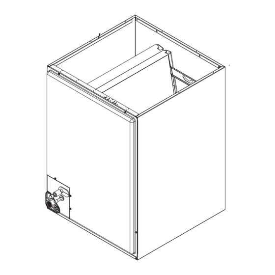
Component Location - Cased Coil CF Model . . . . . . . . . . . . . . . . . . . . 2
Component Location - Cased Coil CM Model . . . . . . . . . . . . . . . . . . . 5
Duct Flanges - Coils CF / CM . . . . . . . . . . . . . . . . . . . . . . . . . . . . . . . . 5
Vertical Applications with Furnaces . . . . . . . . . . . . . . . . . . . . . . . . . . . 5
Vertical Applications with Modular Air Handlers . . . . . . . . . . . . . . . . . . 6
Coil Blow Off Wing Installation . . . . . . . . . . . . . . . . . . . . . . . . . . . . . . . 6
CM Horizontal Right Application with Furnace . . . . . . . . . . . . . . . . . . . 6
CM Horizontal Left Application with Furnace . . . . . . . . . . . . . . . . . . . . 7
Diverter Shroud Installation . . . . . . . . . . . . . . . . . . . . . . . . . . . . . . . . . 7
CM Horizontal Right Application with Modular Air Handler . . . . . . . . . 7
CM Horizontal Left Application with Modular Air Handler . . . . . . . . . . . 7
Vapor Line Grommet . . . . . . . . . . . . . . . . . . . . . . . . . . . . . . . . . . . . . . 9
Recommended Distributor Adjustment . . . . . . . . . . . . . . . . . . . . . . . . . 9
Dimensions - CF Upflow/Downflow Full Cased Coils . . . . . . . . . . . . . . 2
Dimensions - CM Multi-position Full Cased Coils . . . . . . . . . . . . . . . . 3
Coil Air Flow Limits . . . . . . . . . . . . . . . . . . . . . . . . . . . . . . . . . . . . . . . . 4
SECTION I: GENERAL
This instruction covers the installation of the following coils with fur-
naces or MP / ME / MVC modular air handlers.
The coils have sweat connect fittings. All coils are shipped with a low
psi nitrogen holding charge. See Figures 1.
SECTION II: SAFETY
This is a safety alert symbol. When you see this symbol on
labels or in manuals, be alert to the potential for personal
injury.
Understand and pay particular attention to the signal words DANGER,
WARNING, or CAUTION.
DANGER indicates an imminently hazardous situation, which, if not
avoided, will result in death or serious injury.
WARNING indicates a potentially hazardous situation, which, if not
avoided, could result in death or serious injury.
CAUTION indicated a potentially hazardous situation, which, if not
avoided may result in minor or moderate injury. It is also used to alert
against unsafe practices and hazards involving only property damage.
Johnson Controls Unitary Products
LIST OF SECTIONS
REFRIGERANT LINE CONNECTION . . . . . . . . . . . . . . . . . . . . . . . . 6
COIL METERING DEVICES . . . . . . . . . . . . . . . . . . . . . . . . . . . . . . . . 7
INSTRUCTING THE OWNER . . . . . . . . . . . . . . . . . . . . . . . . . . . . . 11
AIR SYSTEM ADJUSTMENT . . . . . . . . . . . . . . . . . . . . . . . . . . . . . 11
INSTALLATION VERIFICATION . . . . . . . . . . . . . . . . . . . . . . . . . . . 12
LIST OF FIGURES
Piston Installation . . . . . . . . . . . . . . . . . . . . . . . . . . . . . . . . . . . . . . . . 9
TXV Installation . . . . . . . . . . . . . . . . . . . . . . . . . . . . . . . . . . . . . . . . . 10
TXV Bulb and Equalizer line Installations . . . . . . . . . . . . . . . . . . . . . 10
Proper Bulb Location for TXV . . . . . . . . . . . . . . . . . . . . . . . . . . . . . . 10
Vertical Temperature Bulb Orientation . . . . . . . . . . . . . . . . . . . . . . . 11
CM "N" & "A" Coil . . . . . . . . . . . . . . . . . . . . . . . . . . . . . . . . . . . . . . . 11
Communicating Port of the Furnace . . . . . . . . . . . . . . . . . . . . . . . . . 12
Wiring Diagram - EEV . . . . . . . . . . . . . . . . . . . . . . . . . . . . . . . . . . . . 12
Drain Traps . . . . . . . . . . . . . . . . . . . . . . . . . . . . . . . . . . . . . . . . . . . . 14
Drain Connections with Furnace . . . . . . . . . . . . . . . . . . . . . . . . . . . . 15
Connections with Modular Air Handler . . . . . . . . . . . . . . . . . . . . . . . 15
LIST OF TABLES
Air Flow Data - Static Pressure Drop for CM Models . . . . . . . . . . . . 12
Air Flow Data - Static Pressure Drop for CF Models . . . . . . . . . . . . 12
Improper installation may create a condition where the operation of
the product could cause personal injury or property damage.
Improper installation, adjustment, alteration, service or maintenance
can cause injury or property damage. Refer to this manual for assis-
tance or additional information, consult a qualified installer or service
agency.
The furnace area must not be used as a broom closet or for any other stor-
age purposes, as a fire hazard may be created. Never store items such as
the following on, near or in contact with the furnace.
1. Spray or aerosol cans, rags, brooms, dust mops, vacuum clean-
ers or other cleaning tools.
2. Soap powders, bleaches, waxes or other Cleaning compounds;
plastic items or containers; gasoline, kerosene, cigarette lighter
fluid, dry cleaning fluids or other volatile fluid.
3. Paint thinners and other painting compounds.
4. Paper bags, boxes or other paper products
Never operate the furnace with the blower door removed. To do so could
result in serious personal injury and/or equipment damage.
WARNING
!
WARNING
!
5292154-UIM-A-0317
ISO 9001
Certified Quality
Management System
Advertisement
Table of Contents

Related Manuals for York CM48C


Summarization of Contents
General and Safety Information
General Installation Overview
This manual covers the installation of full-cased upflow/counterflow and multi-position coils.
Safety Alerts and Signal Words
Explains the safety alert symbol, DANGER, WARNING, and CAUTION signal words.
Installation and Storage Warnings
Highlights risks of improper installation and furnace area storage hazards.
Coil Inspection and Clearances
Coil Inspection and Pressure Check
Instructions for inspecting the coil for damage and pressure upon receipt.
Installation Clearances
Details required clearances for refrigerant piping, servicing, and drain lines.
Coil Dimensions
CF Upflow/Downflow Coil Dimensions
Provides detailed dimensions for CF series coils in a table format.
CM Multi-position Coil Dimensions
Provides detailed dimensions for CM series coils in a table format.
Coil Installation Procedures
Duct Flanges and Transition Angle
Instructions for installing duct flanges and repositioning the transition angle.
Upflow/Downflow Application Installation
Steps for installing CF/CM coils in upflow or downflow configurations.
Horizontal Application Installation
Instructions for installing CM coils in horizontal left and right applications.
Horizontal Right Conversion (CM Models)
Detailed steps for converting CM coils for horizontal right installation.
Direct Duct Installation (CF Models)
Guidance for installing CF coils directly into ductwork without casing.
Duct and Drain Connections
Duct Connection Guidelines
Provides advice on duct system design, installation, and vibration reduction.
Condensate Drain Connections
Instructions for pitching drain lines, preventing freezing, and using secondary drains.
Refrigerant Line Connections
Refrigerant Line Routing and Preparation
Guidance on routing lines, removing grommets, and preparing tubes for brazing.
Brazing and Line Set Installation
Steps for brazing connections, securing lines, and final checks.
Coil Metering Devices
Overview and Preparation
Introduces metering devices and preparation steps before installation.
Piston Installation
Detailed instructions for installing the piston and Schrader valve core.
TXV Installation and Bulb Placement
Steps for installing the TXV, including bulb placement and insulation.
Electronic Expansion Valve (EEV) Coils
Information on EEV coils and connecting communication cables.
System Configuration and Data
Coil Component Identification
Diagrams showing drain pan locations and communicating ports for EEV.
EEV Wiring and Diagnostics
Wiring diagram and LED diagnostic codes for the EEV control.
Coil Cleaning Procedures
Guidelines for safely cleaning the indoor coil using water or approved cleaners.
Owner Instruction and Air System Adjustment
Guidance on registering the warranty and adjusting the air system.
Installation Verification and Airflow Data
Air Flow Data Tables
Tables providing static pressure drop data for CM and CF models.
Installation Verification Checklist
A checklist to verify correct installation of TXV and drain traps.
Drain Trap Configurations
Drain Connections with Furnace
Illustrates trapped and plugged drain connections for furnace applications.
Drain Connections with Modular Air Handler
Illustrates trapped and plugged drain connections for air handler applications.
Need help?
Do you have a question about the CM48C and is the answer not in the manual?
Questions and answers