Table of Contents
Advertisement
DMC-TZ7EB
Model No.
DMC-TZ7EE
DMC-TZ7EF
DMC-TZ7EG
DMC-TZ7EP
DMC-TZ7GC
DMC-TZ7GJ
DMC-TZ7GN
DMC-TZ7SG
DMC-ZS3GD
DMC-ZS3GH
DMC-ZS3GK
DMC-ZS3GT
DMC-ZS3P
DMC-ZS3PC
DMC-ZS3PU
VOL.1
Colours
(S)....................Silver Type (except DMC-TZ7EF/GJ,
ZS3GD)
(K)....................Black Type
(A)....................Blue Type (only DMC-TZ7EE/EG/EP,
ZS3P/PC/PU)
(R)....................Red Type (only DMC-TZ7EB/EF/EG/EP,
ZS3P)
(T)....................Brown Type (only DMC-TZ7EB/EF/EG/
EP/GC/SG, ZS3GH/GK)
©Panasonic Corporation 2009.
Unauthorized copying and distribution is a violation
of law.
ORDER NO.DSC0903018CE
B26
Digital Camera
Advertisement
Chapters
Table of Contents

Related Manuals for Panasonic DMC-TZ7EF


Summarization of Contents
Safety Precautions
General Guidelines
Important safety notices for components, shock prevention, lead dress, protective devices, and leakage current checks.
Leakage Current Cold Check
Procedure to measure resistance between plug and exposed metal parts.
Leakage Current Hot Check
Procedure to measure voltage across a resistor/capacitor for leakage current.
Discharge Capacitor on Flash Top PCB
Procedure to safely discharge high-voltage capacitors on the Flash Top PCB.
Warning
Electrostatic Discharge Prevention (ESD)
Techniques to reduce component damage from static electricity.
Lithium Ion Battery Recycling
Information on recycling lithium-ion batteries for US customers.
AC Cord Safety
Information for Your Safety
Notices regarding copyright, rain/moisture, accessories, and not removing covers.
AC Mains Lead Caution
Safety advice for the 3-pin mains plug, fuse replacement, and wiring code.
Lithium Battery Replacement
Replacement Procedure
Step-by-step guide for replacing the lithium battery.
Service Navigation
Introduction
Purpose of the service manual for understanding and servicing the model.
Lead Free Solder Description
Explanation of lead-free solder composition and properties.
Important Notice (Other than USA/Canada)
Limitations on component-level servicing and recycle module parts.
Define Model Suffix
Methods to identify model suffix using nameplates and safety registration marks.
Initial Settings
Cautions for Initial Settings
Cautions before performing initial settings after PCB replacement.
Initial Settings Procedures
Steps to perform initial settings after main PCB replacement.
Specifications
Camera Specifications
Technical specifications of the digital camera including pixels, zoom, focus, etc.
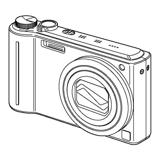
Controls and Components
Location of Controls
Identification of camera controls and components on the exterior.
Mode Dial Functions
Explains the different shooting modes selectable via the mode dial.
About the Battery
Information regarding battery usage and counterfeit packs.
Service Mode
Error Code Memory Function
Function to memorize and display up to 16 error codes for diagnostics.
Error Code List
Detailed list of error codes, their causes, and indications.
Exiting Error Code Display
Procedure to exit the error code display mode.
ICS Function Description
Function to display additional camera settings using Exif data.
How to Read ICS Data
How to interpret jitter alert, ISO sensitivity, and color mode from ICS display.
Exiting ICS Display
Procedure to exit the ICS display mode.
Service Fixture & Tools
Fixtures and Tools List
Lists and illustrates tools and fixtures for servicing.
Main PCB Replacement Adjustments
Note on performing adjustments after replacing the Main PCB.
Service Position and Cables
Lists extension cables and service positions for checking/replacing parts.
Disassembly and Assembly Instructions
Disassembly Flow Chart
Visual flow chart for disassembling the unit.
PCB Location Diagram
Diagram showing the location of various PCBs within the unit.
General Disassembly Procedures
General procedure for disassembling the camera unit.
Case and LCD Unit Removal
Steps to remove rear case and LCD unit.
Main PCB, Front Case, Top Unit Removal
Steps to remove main PCB, front case, and top operation unit.
Sub PCB, Flash, Battery Unit Removals
Steps to remove sub PCB, flash unit, and battery units.
Lens Disassembly Procedures
Steps for disassembling various lens components.
Lens Assembly Procedures
Steps for phase alignment and assembly of lens components.
CCD and Motor Unit Removals
Procedures for removing the CCD unit, zoom, and focus motor units.
Grease Application Method
Points for applying grease to lens unit components.
Measurements and Adjustments
Replaced Part Adjustment Matrix
Chart showing necessary adjustments after replacing specific parts.
Maintenance
Cleaning Surfaces
Instructions for cleaning lens, viewfinder, and LCD panel.
Schematic Diagram Indication
Important Safety Notice
Safety characteristics for components marked with A.
Voltage Chart
Top Operation PCB Voltages
Voltage chart for the Top Operation PCB.
Flash PCB Voltages
Voltage chart for the Flash PCB.
Block Diagram
Overall Block Diagram
Overall block diagram of the camera system.
Schematic Diagrams
Interconnection Diagram
Diagram showing interconnections between major PCBs.
Top Operation Schematic
Schematic diagram for the Top Operation PCB.
Top MIC Schematic
Schematic diagram for the Top Microphone circuit.
Flash Schematic Diagram
Schematic diagram for the Flash circuit.
CCD Flex Schematic Diagram
Schematic diagram for the CCD Flex PCB.
Lens Flex Schematic Diagram
Schematic diagram for the Lens Flex PCB.
Print Circuit Board Layouts
Top Operation PCB Layout
Component and foil side layout of the Top Operation PCB.
Flash PCB Layout
Component and foil side layout of the Flash PCB.
CCD Flex PCB Layout
Component and foil side layout of the CCD Flex PCB.
Lens Flex PCB Layout
Layout of the Lens Flex PCB.
Replacement Parts List
Parts Ordering Notes
Instructions for ordering replacement parts and safety notices.
Exploded Views
Frame and Casing Exploded View
Exploded view of the camera's frame and casing components.
Packing and Accessories Exploded View
Exploded view of packing and accessory components.
Need help?
Do you have a question about the DMC-TZ7EF and is the answer not in the manual?
Questions and answers