Table of Contents
Advertisement
D-E666/EJ620/EJ621/EJ622/
SERVICE MANUAL
Ver 1.4 2001.11
with SUPPLEMENT-1
(9-873-048-81)
System
Compact disc digital audio system
Laser diode properties
Material: GaAIAs
Wavelength : λ= 780 nm
Emission duration: Continuous
Laser output : Less than 44.6 µW
(This output is the value measured at a distance
of 200 mm from the objective lens surface on
the optical pick-up block with 7 mm aperture. )
D-A conversion
1-bit quartz time-axis control
Frequency response
+1
20 - 20,000 Hz
dB (measured by EIAJ CP-
-2
307)
Output (at 4.5 V input level)
Line output (stereo minijack)
Output level 0.7 V rms at 47 kilohms
Recommended load impedance over 10
kilohms
Headphones (stereo minijack)
Approx. 5 mW + Approx. 5 mW at 16 Ω
(Approx. 1 mW + Approx. 1 mW at 16 Ω)*
*For the customers in France
9-873-048-15
Sony Corporation
Personal Audio Company
2001K0200-1
Published by Sony Engineering Corporation
© 2001.11
EJ623/EJ625/EJ626CK
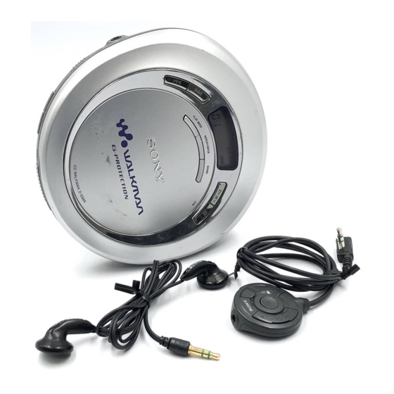
Photo : D-EJ620
SPECIFICATIONS
Power requirements
For the area code of the model you purchased,
check the upper left side of the bar code on the
package.
• Two Sony NC-WMAA rechargeable
batteries: 2.4 V DC,
• Sony NH-WM2AA rechargeable batteries:
2.4 V DC,
• Two LR6 (size AA) batteries: 3 V DC
• AC power adaptor (DC IN 4.5 V jack):
US, Canadian, C&SA, MX model:
120 V, 60 Hz
AEP, FR, G, EE, E13, G model:
220 - 230 V, 50/60 Hz
UK, 3AEP7 model: 230 - 240 V, 50 Hz
AUS model: 240 V, 50 Hz
JEW, E33 model: 100 - 240 V, 50/60 Hz
HK model: 220 V, 50/60 Hz
AR, CH model: 220 V, 50 Hz
• Sony DCC-E345 car battery cord for use on
car battery : 4.5V DC
D-EJ621/EJ622/EJ625/EJ626CK
Canadian Model
Australian Model
D-EJ621/EJ625/EJ626CK
D-EJ620/EJ621/EJ623/EJ625/EJ626CK
Chinese Model
Tourist Model
Model Name Using Similar Mechanism D-EJ711
CD Mechanism Type
Optical Pick-up Type
Battery life* (approx. hours)
(When you use the CD player on a flat and
stable surface.)
Playing time varies depending on how the CD
player is used.
When using
G-PROTECTION function
Tow NC-WMAA
(charged for about 3 hours**)
NH-WM2AA
(charged for about 5 hours**)
Two Sony alkaline batteries
LR6 (SG)
*
Measured value by the standard of EIAJ
(Electronic Industries Association of Japan).
** Charging time varies depending on how the
rechargeable battery is used.
Operating temperature
5°C - 35°C (41°F - 95°F)
PORTABLE CD PLAYER
US Model
UK Model
E Model
AEP Model
D-EJ621/EJ625
D-E666
CDM-3123EBA
DAX-23E
on
off
10
8
21
18
36
32
– Continued on page 2 –
Advertisement
Table of Contents

Related Manuals for Sony Walkman D-EJ622


Summarization of Contents
SPECIFICATIONS
System
Details about the compact disc digital audio system.
Laser Diode Properties
Information on laser diode material, wavelength, and output.
D-A Conversion
Describes the 1-bit quartz time-axis control for D-A conversion.
Frequency Response
Specifies the frequency response range and measurement method.
Power Requirements
Lists power sources and voltage requirements for different regions.
Battery Life
Provides approximate battery life with and without G-Protection.
SERVICING NOTES
Handling Optical Pick-up Block
Guidelines for safely handling the optical pick-up block and base unit.
Laser Diode Emission Check
Procedures for checking laser diode emission safely.
Before Replacing Pick-up Block
Steps to take before replacing the optical pick-up block.
Laser Diode Checking Methods
Methods for visually checking the laser diode emission.
GENERAL
Locating Controls
Identifies and describes controls for the CD player's front and inside.
DISASSEMBLY
Cabinet, Main Board
Procedures for disassembling cabinet parts and the main board.
MD ASSY
Steps for disassembling the MD ASSY.
Motor Assy, Turn Table
Disassembly of the motor assembly for the turn table.
Motor Assy (Sled), Optical Pick-up
Disassembly of motor assembly for sled and optical pick-up.
Lid, Upper, Switch Unit
Disassembly of the upper lid and switch unit.
ELECTRICAL ADJUSTMENTS
Precautions for Check
Important precautions to follow during electrical checks.
Focus Bias Check
Procedure for checking and adjusting focus bias.
RF Signal Waveform Check
How to check the RF signal reference waveform (eye pattern).
DIAGRAMS
Explanation of IC Terminals
Detailed explanation of IC terminals and their functions.
Block Diagram
Provides a block diagram of the system's components and connections.
PRINTED WIRING BOARDS
Main Board (Side A)
Layout and component placement for the main board, side A.
Main Board (Side B)
Layout and component placement for the main board, side B.
SCHEMATIC DIAGRAM
Main Section (1/2)
First part of the main schematic diagram detailing circuit connections.
Main Section (2/2)
Second part of the main schematic diagram detailing circuit connections.
IC Block Diagrams
Block diagrams for key integrated circuits used in the device.
Waveforms
Illustrates typical waveforms at various test points.
EXPLODED VIEWS
Cabinet Section
Exploded view of the cabinet and its components.
Optical Pick-up Section
Exploded view of the optical pick-up section and its parts.
ELECTRICAL PARTS LIST
Main
Comprehensive list of electrical parts for the main board.
Components Identified by Mark ▲
Lists components marked as critical for safety and their part numbers.
Accessories & Packing Materials
Lists accessories and packing materials included with the product.
SUPPLEMENT-1
Model Addition
Details new models added and their reference models.
DEFFERENCE PARTS LIST
Exploded Views
Lists differences in parts for exploded views across various models.
REVISION HISTORY
Revision Details
Records of revisions made to the service manual with dates and descriptions.
Need help?
Do you have a question about the Walkman D-EJ622 and is the answer not in the manual?
Questions and answers