Table of Contents
Troubleshooting

Related Manuals for Mitsubishi QJ71BR11


Summarization of Contents
Safety Precautions
Design Precautions
Precautions related to designing the system and handling potential errors.
Installation Precautions
Precautions for safely installing modules, including mounting and securing.
Wiring Precautions
Precautions for proper grounding, wiring, and cable management during installation.
Setup and Maintenance Precautions
Precautions for online operations, module handling, cleaning, and static electricity discharge.
Disposal Precautions
Guidance on treating the product as industrial waste when disposing of it.
Overview
Overview
General overview of the MELSECNET/H remote I/O network system and its relation to MELSECNET/10.
Features
Details the advantages of the MELSECNET/H remote I/O network, including speed, scale, and flexibility.
Abbreviations and Marking Formats
Defines abbreviations and explains the marking format used throughout the manual.
Version D Function Updates
Lists additional and changed functions for network modules with Function Version D.
System Configuration
Single Remote I/O Networks
Details the configuration of optical loop and coaxial cable bus systems for single remote I/O networks.
Multiple Remote I/O Network (QnPHCPU)
Explains the configuration of multiplexed remote I/O networks using QnPHCPU, including master and sub-master stations.
Redundant System Configuration (QnPRHCPU)
Details the setup for redundant systems using QnPRHCPU, covering control and standby systems.
Multiple Remote I/O Network Configuration
Describes the configuration of multiple remote I/O networks, allowing multiple networks per CPU.
System Configuration Precautions
Important considerations for configuring remote I/O systems, including network mixing and applicable modules.
Using Multiple CPU Systems
Guidelines for configuring remote I/O networks when utilizing multiple CPU systems.
Checking Module Version and Serial Number
Instructions for checking the function version and serial number of network modules using the rating plate or GX Developer.
Specifications
Performance Specifications
Details the performance specifications for optical loop systems, including device ranges, speed, and distance.
Optical Loop System Performance
Presents detailed performance data for optical loop systems, covering links, points, speed, and distance.
Coaxial Cable System Performance
Details the performance specifications for coaxial cable systems, including links, points, speed, and distance.
Optical Fiber Cable Specifications
Provides specifications for optical fiber cables used in MELSECNET/H loop systems, including interstation distance and loss.
Coaxial Cable Specifications
Lists the specifications for coaxial cables used in the coaxial bus system, including diameter and bend radius.
Function Specifications
Introduces the various functions of the MELSECNET/H remote I/O network, categorized into basic and application functions.
Cyclic Transmission Function
Explains how cyclic transmission works for input/output modules and intelligent function modules.
RAS Functions
Details enhanced RAS functions like automatic return, loopback, station detach, and online module change.
Link Data Transfer Time
Explains the method for calculating link data send/receive and transmission delay times.
Setup and Procedures
Pre-Operation Procedures
Outlines the sequence of steps required to start data link operation, from module settings to debugging.
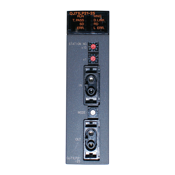
Network Module Names and Settings
Details the names and settings for optical loop and coaxial cable modules, including LED displays and switches.
Module Installation and Removal
Provides step-by-step instructions for installing and uninstalling modules from the base unit.
Stopping the CPU for Safety
Procedure to stop the CPU module to prevent unintentional outputs during setup or maintenance.
Checking Input Power Supply
Ensures the power supply voltage to the power supply module is within the specified range.
Powering On Procedures
Steps for powering on the system, including checking POWER and RUN LEDs.
Offline Network Module Tests
Describes three offline tests (Self-loopback, Internal Self-loopback, Hardware) to check module and cable integrity.
Cable Connections
Provides detailed instructions and precautions for connecting optical fiber and coaxial cables.
Optical Loop System Cable Connection
Explains how to connect optical fiber cables, including precautions and installation steps.
Coaxial Bus System Cable Connection
Details precautions and methods for connecting coaxial cables in a bus system.
GX Developer Offline Tests
Explains how to perform forward loop/reverse loop tests using GX Developer to check cable and module connections.
Forward Loop/Reverse Loop Test
Describes how to conduct forward and reverse loop tests for checking hardware and cable connectivity.
Network Diagnostics (Online Test)
Details online tests available through GX Developer for checking network status, loop tests, and communication.
Loop Test (Optical Loop)
Checks the line status of the optical loop system and the station executing loopback.
Setup Confirmation Test
Checks switch settings of network modules for duplicate control stations and network number matching.
Station Order Check Test (Optical Loop)
Checks connected station numbers in the optical loop system and verifies connection orders.
Communication Test
Verifies normal data communication between host and destination stations, checking routing parameters.
Parameter Settings
Remote Master Station Parameters
Guides on setting network parameters for the remote master station CPU module.
Setting Module Cards and Network Type
Details how to set the network type and station type for each module in the MELSECNET/H network system.
Network Settings
Configuration of starting I/O No., network No., total stations, group No., and mode for MELSECNET/H.
Common Parameters
Setting of common parameters for LB, LW, LX, and LY cyclic transmission ranges.
Supplemental Settings
Optional settings in common parameters for precise usage, including constant scan and return station settings.
Network Refresh Parameters
Configuration of parameters for transferring link device data to CPU module devices for sequence programs.
Valid Modules for Cross-Station Access
Specifies modules that can be relayed for data communication requests when the network number cannot be specified.
Redundant System Settings
Procedure for setting the same mode for the multiplexed remote sub-master station as the master station.
Remote I/O Station Parameters
Guides on setting PLC parameters, network parameters, and remote password for remote I/O modules.
Possible Remote I/O Station Parameters
Lists parameters that can be set on the remote I/O station and written to the remote I/O module.
Programming
Programming Precautions
Precautions for creating programs using network data, including interlock signals.
Interlock Signals
Lists interlock signal devices used in sequence programs and their assignments.
Program Example
Illustrates an interlock in the communication program using link status of host and other stations.
Cyclic Transmission
Explains cyclic transmission for remote I/O networks, including 32-bit data guarantee and block guarantee.
32-bit Data Guarantee
Details the conditions for automatically guaranteeing 32-bit data precision.
Block Guarantee for Cyclic Data
Explains how to enable block guarantee for cyclic data per station using parameter settings.
I/O and Intelligent Module Communication
Covers settings for CPU module to communicate with remote I/O station modules using cyclic transmission.
Dedicated Link Instructions
Lists the instructions that can be used for MELSECNET/H, with details on format and examples.
Using Link Special Relays and Registers
Explains how to use Link Special Relays (SB) and Link Special Registers (SW) for data linking information and troubleshooting.
Application Functions
Transient Transmission Function
Performs data communication only when requested between stations.
Dedicated Link Instructions
Details the REMFR/REMTO instructions for reading/writing buffer memory of intelligent function modules.
Remote I/O Station System Monitor
Enables monitoring and diagnosis of intelligent function modules on remote I/O stations using GX Developer.
Device Test for Remote I/O Stations
Allows testing of input/output devices of sequence programs on remote I/O stations without affecting the online system.
Multiplex Transmission Function (Optical Loop)
Enables high-speed communications using duplex transmission paths in the optical loop system.
Return Sequence Station Number Setting
Allows setting the number of stations for which communication errors during one link scan can perform return sequence.
Reserved Station Function
Handles stations to be connected in the future as stations with communication errors.
Interrupt Settings
Allows checking interrupt conditions at data reception from remote I/O stations and issuing interrupt requests.
I/O Assignment Function
Provides a convenient way to change I/O response time, error time output mode, and intelligent function module settings.
Stopping/Restarting Cyclic Transmission and Link Refreshing (Network Test)
Uses GX Developer's network test to stop and restart cyclic data and link refreshing.
Multiplexed Remote Master Function (QnPHCPU)
Allows the multiplexed remote sub-master station to take control of remote I/O stations when the master station fails.
Redundant System Multiplexed Master Function (QnPRHCPU)
Controls I/O modules and intelligent function modules in a redundant system.
Backup Function for Master Operation on System Switching
Details how master operation is backed up during system switching between control and standby systems.
Master Operation by Control System Startup Station
Explains master operation performed by the station that starts up as the control system.
System Switching Request Function
Allows the control system to issue a switching request to the standby system upon detecting a data link error.
Access Function by Specifying Control/Standby System
Enables access to QnPRHCPU by specifying control or standby system via GX Developer.
Remote Password Function
Prevents unauthorized remote access to remote I/O modules and PLC CPUs by setting a remote password.
Troubleshooting
Network Diagnostics (Network Monitor)
Checks network line status, host information, other station information, and error history.
Host Information
Displays entire network connection status and host status.
Other Station Information
Checks communication, data link, parameter, CPU, loop, and reserved station status of each station.
Network Monitor Details
Provides detailed information on network, remote master station, and data link status.
Error History Monitor
Checks forward/reverse loop errors, communication errors, and transient transmission errors.
Troubleshooting Steps
Provides a flowchart for troubleshooting network module and host issues.
Initial Checks
Lists essential checks for diagnosing network and module issues, including LED status and parameter settings.
Troubleshooting Data Link Failures (Entire System)
Steps to diagnose issues when data linking fails across the entire system.
Troubleshooting Data Link Issues (Reset/Power Off)
Addresses issues where data link is disabled due to station resets or power cycles.
Troubleshooting Specific Station Data Link Failures
Steps to diagnose data link failures for individual stations.
Troubleshooting Abnormal Transmission/Reception Data
Diagnosing issues when cyclic or transient transmission data is abnormal.
Troubleshooting Incomplete Dedicated Link Instructions
Steps to take when dedicated link instructions fail to complete.
Troubleshooting Redundant System I/O Network Issues
Addresses problems with multiplexed remote I/O networks in redundant systems.
Checking Fiber-Optic Cable Connections (Online)
Procedure for checking incorrect fiber-optic cable connections during online operation.
Error Codes
Provides a list of MELSECNET/H error codes, their meanings, causes, and corrective actions.
MELSECNET/H Error Code List
Comprehensive list of MELSECNET/H error codes, their descriptions, and corrective actions.
Appendix
Precautions for MELSECNET/10 to MELSECNET/H Transition
Details precautions for switching from MELSECNET/10 to MELSECNET/H remote I/O networks.
Link Special Relay (SB) List
Lists and explains the function of link special relays (SB) used for data linking status and troubleshooting.
Link Special Register (SW) List
Lists and explains the function of link special registers (SW) for data linking information.
Special Registers (SD) for Remote I/O Modules
Details the specifications of special registers (SD) for remote I/O modules, including their meanings and usage.
Discontinued Models for Remote I/O Stations
Lists discontinued Q series models applicable to remote I/O stations and their restrictions.
External Dimensions
Provides external dimension drawings for various network modules like QJ71LP21, QJ71BR11, QJ72LP25, QJ72BR15.
QJ71LP21-25, QJ71LP21G, QJ71LP25GE Dimensions
External dimensions for QJ71LP21-25, QJ71LP21G, and QJ71LP25GE modules.
QJ71LP21S-25 Dimensions
External dimensions for the QJ71LP21S-25 module.
QJ71BR11 Dimensions
External dimensions for the QJ71BR11 module.
QJ72LP25 Series Dimensions
External dimensions for QJ72LP25-25, QJ72LP25G, and QJ72LP25GE modules.
QJ72BR15 Dimensions
External dimensions for the QJ72BR15 module.
Warranty Information
Gratis Warranty Terms and Range
Details the one-year gratis warranty term and specifies cases where repairs are charged.
Post-Discontinuation Repair Terms
Explains Mitsubishi's policy for repairs for seven years after product discontinuation.
Overseas Service
Notes that overseas repairs are handled by Mitsubishi's local overseas FA Center with potentially different conditions.
Warranty Liability Exclusions
Mitsubishi's liability exclusion for damages like lost profits, accidents, or maintenance costs.
Product Specification Changes
States that specifications in catalogs and manuals are subject to change without notice.
Product Application Guidelines
Specifies usage conditions and excludes applications where human life or property could be greatly affected.
Need help?
Do you have a question about the QJ71BR11 and is the answer not in the manual?
Questions and answers