Table of Contents
Advertisement
HRV / ERV INSTALLATION AND
OPERATING INSTRUCTIONS
790 Rowntree Dairy Road,
Woodbridge, ON Canada L4L 5V3
t: 905.851.6701
f: 905-851.8376
e: info@reversomatic.com
Toll Free: 1.800.810.3473 (Canada)
1.800.499.5073 (U.S.A.)
www.reversomatic.com
Deluxe Series
RHRV-D100A
Aluminum Core
RHRV-D100P
Polypropylene Core
RERV-D100
Enthalpy Core
C
®
2100
CERTIFIED
model:
®
US
Advertisement
Table of Contents

Related Manuals for Reversomatic RERV-D100


Summary of Contents for Reversomatic RERV-D100
- Page 1 HRV / ERV INSTALLATION AND OPERATING INSTRUCTIONS Deluxe Series model: RHRV-D100A Aluminum Core RHRV-D100P Polypropylene Core RERV-D100 Enthalpy Core 790 Rowntree Dairy Road, Woodbridge, ON Canada L4L 5V3 t: 905.851.6701 f: 905-851.8376 ® e: info@reversomatic.com ® 2100 Toll Free: 1.800.810.3473 (Canada) 1.800.499.5073 (U.S.A.)
-
Page 2: Table Of Contents
3. Unit has to be installed in accordance to National and • Annual Maintenance Local Building Code. 4. When leaving house for a long period of time (more than Troubleshooting two weeks), a responsible person should check if unit operates adequately. Climate Zone www.reversomatic.com • info@reversomatic.com... -
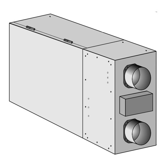
Page 3: Parts List
Parts List Optional Parts:... -
Page 4: Wiring Diagram
Wiring Diagram Control Board HRV/ERV CHASSIS Control Board Low Voltage From Safety Switch Side Connections (Mounted on HRV/ERV Housing) Connection to the (RED) (RED) Furnace, Fan-coil or Heat Pump (WHITE) Relay Output: SPDT Max. Recommended current: 2A Connection to wall control units and timer switches SPLICE... -
Page 5: Furnace / Fan-Coil / Heat Pump Interlock
Wiring Diagram (cont’d) Furnace / Fan-Coil / Heat Pump Interlock: W A R N I N G Never connect a 120 volt AC circuit to the terminals of the furnace /fan-coil/heat pump interlock (Standard Wiring). Only use the low voltage class 2 circuit. Standard Interlock Wiring THERMOSTAT TERMINALS FOUR WIRE... -
Page 6: Hrv/Erv Operational Modes Functionality
HRV/ERV Operational Modes Functionality Off Mode: HRV/ERV fans are off. Defrost damper is closed to prevent cold air from entering the unit. Normal Mode: In Normal mode HRV/ERV fans run and the unit exchanges indoor air with outdoor air. The airflow exchange can be adjusted in four preset airflow values. -
Page 7: Programming Instructions For Wall Control Unit (Wc100)
Programming Instructions for Wall Control Unit (WC100) Normally there will be only one Wall Control Unit connected to Control Board. Multi Wall Control Unit (up to three) is also supported (see page 2). All Wall Control Units will have the same priorities over each other. It means that if multiple Wall Control Units command Control Board differently, the latest command will be executed by the Control Board. -
Page 8: Setting Internal Programming Parameters
Map 4-6 are for Polypropylene Core (RHRV-D100P). Map 7-9 are for ERV Core (RERV-D100). Factory programmed default DEFR values are Map-1 for RHRV-D100A, Press both + and - buttons for Map-4 for RHRV-D100P & Map-7 PROGRAM 4 sec. Unit switches to TIMER for RERV- D100. -
Page 9: Displaying Errors
Programming Instructions for Wall Control Unit (cont’d) The changed exhaust fan speed After pressing the MODE button, PROGRAM is stored in non-volatile memory the unit switches to Airflow which will be used from now on Balancing disable/enable setting. for the current airflow settings The current value is enabled. -
Page 10: Hrv And Erv Typical Installations
FRESH AIR EXHAUSTED AIR Note: • All Exhaust Vents must be installed min. 5 ft away from sidewalls Note: All HRV / ERV must be balanced in the field. (Models: RHRV-D100A, RHRV-D100P and RERV-D100 c/w auto balancing are automatically balanced) -
Page 11: Horizontal
Also make sure you have proper defrost on wall - controller according to HRV / ERV model no./ core type. Map 1-3 are for Aluminum Core (RHRV-D100A). Map 4-6 are for Polypropylene / Plastic Core (RHRV-D100P). Map 7-9 are for ERV / Enthalpy Core (RERV-D100). -
Page 12: Access Door Installation
For more info visit http://www.reversomatic.com/HRV&ERV/Accessories Drain Connection During defrost cycle the HRV unit may produce some condensation and the water should flow into a nearby drain. -
Page 13: Air Flow Balancing
Air Flow Balancing For units without built-in true Automatic Electronic Air-balancing and for cross verification only Balancing Procedure It is required to have balanced air flows in an HRV/ERV. The volume of air brought in from the outside must equal the volume of air exhausted by the unit while running at normal speed. If the air flows are not properly balanced, then: •... -
Page 14: Maintenance
Air Flow Balancing (cont’d) DUCT DIAM CROSS SECTION AREA P" Note:(Option #2) Ø5 Ø6 *For balancing, extension box cover plate is 5" 0.136 sq. ft. 0.010 0.004 provided with 3 holes on supply side and 3 6" 0.196 sq. ft. 0.012 0.006 holes on exhaust side. -
Page 15: Annual Maintenance
Maintenance (cont’d) Annual Maintenance Repeat steps 1 to 5 from the previous section and continue with the following steps: 1. Clean the HRV and ERV core: - Remove filters, Loosen the core locking bracket , Remove the core, carefully grip ends of core and pull evenly outward ATTENTION - HRV Core >... -
Page 16: Climate Zone
U.S. Department of Energy climate zones map 790 Rowntree Dairy Road, Woodbridge ON, Canada L4L 5V3 Tel: 905-851-6701 • Fax: 905-851-8376 • info@reversomatic.com Toll Free: 1.800.810.3473 (Canada) • 1.800.499.5073 (U.S.A.) w w w . r e v e r s o m a t i c . c o m...
Need help?
Do you have a question about the RERV-D100 and is the answer not in the manual?
Questions and answers