Sony STR-K4800P - A/v Receiver Service Manual
Hide thumbs
Also See for STR-K4800P - A/v Receiver:
- Operating instructions manual (48 pages) ,
- Limited warranty (1 page)
Table of Contents
Advertisement
STR-DE497P/K4800P/K5800P
QQ
3 7 63 1515 0
SERVICE MANUAL
Ver 1.1 2004. 10
• STR-DE497P/K4800P/K5800P
are the FM/AM receiver section in
HT-DDW760/4800DP/5800DP.
Manufactured under license from Dolby Laboratories.
"Dolby", "Pro Logic" and the double-D symbol are
trademarks of Dolby Laboratories.
"DTS" and "DTS Digital Surround" are registered
trademarks of Digital Theater Systems, Inc.
TE
L 13942296513
AUDIO POWER SPECIFICATIONS
POWER OUTPUT AND TOTAL HARMONIC
DISTORTION:
(Models of area code US only)
With 6 ohm loads, both channels driven, from
120 – 20,000 Hz; rated 80 watts (STR-K5800P)/
60 watts (STR-K4800P) per channel minimum
RMS power, with no more than 0.7 % total
harmonic distortion from 250 milliwatts to rated
output.
Amplifier section
1)
Power Output
Models of area code US
(6 ohms 1 kHz, THD 10 %)
STR-K5800P:
STR-K4800P:
Models of area code CND
(6 ohms 1 kHz, THD 0.7 %)
(6 ohms 1 kHz, THD 10 %)
www
.
Sony Corporation
9-879-027-02
2004J04-1
Audio Group
© 2004. 10
Published by Sony Engineering Corporation
http://www.xiaoyu163.com
FRONT
2)
: 120 W/ch
2)
CENTER
: 120 W
SURR
2)
: 120 W/ch
FRONT
2)
: 100 W/ch
2)
CENTER
: 100 W
SURR
2)
: 100 W/ch
2)
FRONT
: 80 W/ch
CENTER
2)
: 80 W
2)
SURR
: 80 W/ch
2)
FRONT
: 100 W/ch
2)
CENTER
: 100 W
SURR
2)
: 100 W/ch
x
ao
u163
y
i
http://www.xiaoyu163.com
2 9
8
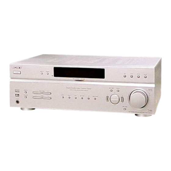
Photo: STR-K5800P
SPECIFICATIONS
Q Q
3
6 7
1 3
1 5
Models of area code AEP, UK
(6 ohms 1 kHz, THD 0.7 %)
(6 ohms 1 kHz, THD 10 %)
1) Measured under the following conditions:
Area code
US, CND
AEP, UK
2) Depending on the sound field settings and the
source, there may be no sound output.
Inputs (Analog)
MULTI CH IN
*
, CD,
MD/TAPE,
VIDEO 1, 2, DVD
Inputs (Digital)
DVD (Coaxial)
VIDEO 2 (Optical)
FM STEREO/FM-AM RECEIVER
co
.
9 4
2 8
US Model
STR-K4800P/K5800P
Canadian Model
STR-K4800P
AEP Model
UK Model
STR-DE497P
0 5
8
2 9
9 4
2 8
FRONT
2)
: 80 W/ch
2)
CENTER
: 80 W
SURR
2)
: 80 W/ch
FRONT
2)
: 100 W/ch
CENTER
2)
: 100 W
2)
SURR
: 100 W/ch
Power requirements
120 V AC, 60 Hz
230 V AC, 50 Hz
Sensitivity: 800 mV
Impedance: 50 kiloohms
Sensitivity: –
Impedance: 75 ohms
Sensitivity: –
Impedance: –
– Continued on next page –
m
9 9
9 9
1
Advertisement
Table of Contents

Related Manuals for Sony STR-K4800P - A/v Receiver


Summarization of Contents
Audio Power Specifications
Power Output and Total Harmonic Distortion
Details power output and harmonic distortion for different models.
Specifications
Measurement Conditions and Input Specs
Specifies conditions for power output measurements and input types.
Tuner Sections
FM Tuner Details
Details tuning range, antenna, and intermediate frequency for FM.
AM Tuner Details
Details tuning range, antenna, and intermediate frequency for AM.
General Specifications
Power Requirements and Consumption
Lists power requirements and consumption details for various conditions.
Dimensions and Mass
Provides physical dimensions and weight of the unit.
Safety Check-out
AC Leakage Test Procedure
Details procedure for testing AC leakage from metal parts to ground.
Model Identification
Back Panel Identification
Shows model identification table for the back panel.
General Information
Main Unit Details
Refers to main unit details for STR-DE497P and STR-K4800P/K5800P.
Disassembly Procedures
Case Disassembly
Details the procedure for disassembling the case.
Front Panel Section Disassembly
Details the procedure for disassembling the front panel.
Back Panel Disassembly
Details the procedure for disassembling the back panel.
Board Disassembly
Details disassembly for Digital, Standby, and Main boards.
Diagrams
Circuit Boards Location
Illustrates the physical location of each circuit board.
Block Diagrams
Covers Tuner/Audio, Digital, Video, and Power sections.
Schematic Diagrams
Provides schematics for Main, Digital, Video, and Power sections.
IC Block Diagrams
Block diagrams for integrated circuits used in the unit.
Exploded Views
Case Section Exploded View
Exploded view of the unit's case with part numbers.
Remote Control Operations
Remote Battery Insertion and Usage Tips
Guide to inserting batteries and usage tips for the remote.
Remote Button Descriptions
Detailed description of each button on the remote control.
Disassembly Procedures
2-1. Case Disassembly
Detailed steps for disassembling the unit's case.
Disassembly Procedures
2-2. Front Panel Section Disassembly
Detailed steps for disassembling the front panel section.
2-3. Back Panel Disassembly
Detailed steps for disassembling the back panel.
Disassembly Procedures
2-4. Digital Board Disassembly
Detailed steps for disassembling the digital board.
2-5. Standby Board Disassembly
Detailed steps for disassembling the standby board.
Disassembly Procedures
2-6. Main Board Disassembly
Detailed steps for disassembling the main board.
Test Modes
Factory Preset Mode
Procedure to reset all preset contents to default values.
AM Channel Step Selection Mode
Procedure to select AM tuning scale step.
Speaker Size Selection Mode
Procedure to select speaker size setting.
Display Test Modes
Tests fluorescent display segments and software versions.
Special Modes
Covers Sound Field Clear, Key Check, Auto-betical, and Command Mode.
Diagrams
Circuit Boards Location
Illustrates the physical location of each circuit board.
Waveforms (Digital Board)
Displays waveforms for the digital board signals.
Exploded Views
5-1. Case Section Exploded View
Exploded view of the unit's case with part numbers.
Electrical Parts List
Capacitor List
List of capacitors with part numbers and specifications.
Parts List - Digital Display
IC List
List of integrated circuits with part numbers.
Jack List
List of connectors and jacks with part numbers.
Transistor List
List of transistors with part numbers.
Resistor List
List of resistors with part numbers.
Parts List - Digital Display
Resistor List
List of resistors with part numbers.
Parts List - Digital Display
Resistor List
List of resistors with part numbers.
Connector List
List of connectors with part numbers.
Diode List
List of diodes with part numbers.
Transistor List
List of transistors with part numbers.
Capacitor List
List of capacitors with part numbers.
Parts List - Display, Headphone, Main
Connector List
List of connectors with part numbers.
Jack List
List of jacks with part numbers.
Capacitor List
List of capacitors with part numbers.
Parts List - Main
Capacitor List
List of capacitors with part numbers.
Parts List - Main
IC List
List of integrated circuits with part numbers.
Transistor List
List of transistors with part numbers.
Parts List - Main
Resistor List
List of resistors with part numbers.
Parts List - Main
Resistor List
List of resistors with part numbers.
Parts List - Main Power Standby
Connector List
List of connectors with part numbers.
Diode List
List of diodes with part numbers.
Transistor List
List of transistors with part numbers.
Resistor List
List of resistors with part numbers.
Relay List
List of relay components.
Transformer List
List of transformer components.
Parts List - Standby Tuning Video
Resistor List
List of resistors with part numbers.
Miscellaneous Parts
Lists miscellaneous parts like wires and fuses.
Capacitor List
List of capacitors with part numbers.
Connector List
List of connectors with part numbers.
IC List
List of integrated circuits with part numbers.
Jack List
List of jacks with part numbers.
Need help?
Do you have a question about the STR-K4800P - A/v Receiver and is the answer not in the manual?
Questions and answers