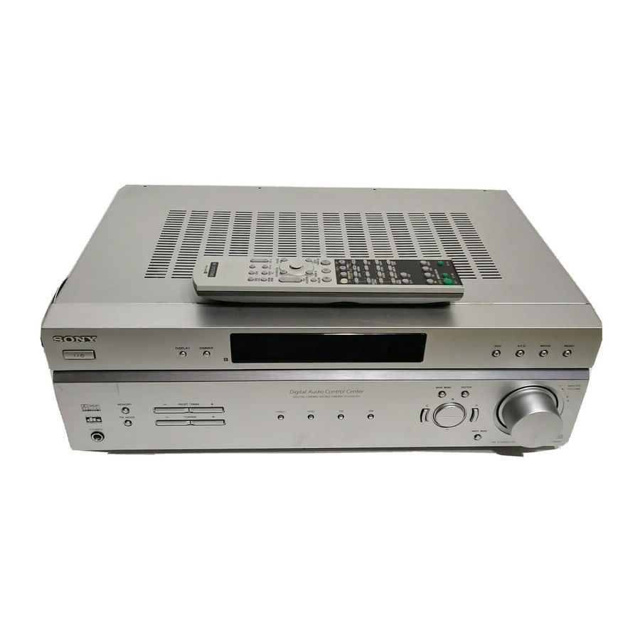
Sony STR-K660P Service Manual
Hide thumbs
Also See for STR-K660P:
- User manual (36 pages) ,
- Operating instructions (2 pages) ,
- Limited warranty (1 page)
Table of Contents
Advertisement
Quick Links
QQ
3 7 63 1515 0
SERVICE MANUAL
Ver 1.0 2004.02
• STR-K660P is the tuner and the amplifier
section in HT-DDW660.
Manufactured under license from Dolby Laboratories.
"Dolby", "Pro Logic" and the double-D symbol are trademarks of
Dolby Laboratories.
"DTS" and "DTS Digital Surround" are registered trademarks of
Digital Theater Systems, Inc.
TE
L 13942296513
AUDIO POWER SPECIFICATIONS
POWER OUTPUT AND TOTAL HARMONIC
DISTORTION:
(Models of area code U only)
With 6 ohm loads, both channels driven, from
120 − 20,000 Hz; rated 50 watts per channel
minimum RMS power, with no more than 0.7%
total harmonic distortion from 250 milliwatts to
rated output.
Amplifier section
Power Output
Models of area code U
(6 ohms 1 kHz, THD 10%)
(6 ohms 100 Hz, THD 10%)
Models of area code SP, MX, E51
(6 ohms 1 kHz, THD 0.7%)
(6 ohms 100 Hz, THD 0.7%)
www
.
Sony Corporation
9-877-522-01
2004B1678-1
Home Audio Company
© 2004.02
Published by Sony Engineering Corporation
http://www.xiaoyu163.com
1)
2)
FRONT
: 70 W/ch
2)
CENTER
: 70 W
2)
SURR
: 70 W/ch
SUB WOOFER
2)
FRONT
: 50 W/ch
2)
CENTER
: 50 W
2)
SURR
: 50 W/ch
SUB WOOFER
x
ao
u163
y
i
http://www.xiaoyu163.com
STR-K660P
2 9
8
SPECIFICATIONS
Q Q
3
6 7
1 3
1 5
(6 ohms 1 kHz, THD 10%)
(6 ohms 100 Hz, THD 10%)
1) Measured under the following conditions:
Area code
U, MX
SP
E51
2) Depending on the sound field settings and the
source, there may be no sound output.
Inputs (Analog)
DVD, VIDEO
2)
: 70 W
2)
: 50 W
FM STEREO FM-AM RECEIVER
co
.
9 4
2 8
US Model
E Model
0 5
8
2 9
9 4
2 8
2)
FRONT
: 70 W/ch
2)
CENTER
: 70 W
2)
SURR
: 70 W/ch
2)
SUB WOOFER
: 70 W
Power requirements
120 V AC, 60 Hz
230 V AC, 50 Hz
240 V AC, 50 Hz
Sensitivity: 800 mV
Impedance: 50 kiloohms
— Continued on next page —
m
9 9
9 9
Advertisement
Table of Contents

Related Manuals for Sony STR-K660P


Summary of Contents for Sony STR-K660P
- Page 1 3 7 63 1515 0 SERVICE MANUAL US Model E Model Ver 1.0 2004.02 • STR-K660P is the tuner and the amplifier section in HT-DDW660. Manufactured under license from Dolby Laboratories. “Dolby”, “Pro Logic” and the double-D symbol are trademarks of Dolby Laboratories.
- Page 2 STR-K660P 3 7 63 1515 0 Inputs (Digital) General Sensitivity: − Power requirements DVD (Coaxial) Impedance: 75 ohms Area code Power requirements Sensitivity: − VIDEO (Optical) , MX 120 V AC, 60 Hz Impedance: − 220 − 230 V AC, 50/60 Hz...
-
Page 3: Tel 13942296513
COMPONENTS IDENTIFIED BY MARK 0 OR DOTTED LINE WITH MARK 0 ON THE SCHEMATIC DIAGRAMS AND IN THE PARTS LIST ARE CRITICAL TO SAFE OPERATION. REPLACE THESE COMPONENTS WITH SONY PARTS WHOSE PART NUMBERS APPEAR AS SHOWN IN THIS MANUAL OR IN SUPPLEMENTS PUBLISHED BY SONY. -
Page 4: Table Of Contents
STR-K660P 3 7 63 1515 0 TABLE OF CONTENTS 1. GENERAL ··································································· 2. TEST MODE ······································································ 9 3. DIAGRAMS 3-1. Circuit Board Location ··············································· 10 3-2. Block Diagrams – MAIN Section – ··························· 12 – DISPLAY/POWER Section – ································· 13 3-3. -
Page 5: General
STR-K660P SECTION 1 GENERAL This section is extracted 3 7 63 1515 0 from instruction manual. M - Z NUMBERS AND SYMBOLS ALPHABETICAL ORDER 2CH (button/indicator) 6 (17, MAIN MENU qg (11, 20, 22, 24) A - L 19, 21) MASTER VOLUME −/+ q;... - Page 6 STR-K660P 3 7 63 1515 0 Remote Operations Function Remote button Button description ALT wa Remote When ALT button lights up, it changes the remote key function to activate those buttons with orange printing. TV ?/1 AV ?/1 AM qg Receiver To select the AM band.
- Page 7 DVD player Changes the subtitles. MEMORY Receiver Stores the radio stations. SYSTEM Receiver/ Turns off the receiver STANDBY TV/VCR/ and other Sony audio/ MUTING Receiver Mutes the sound from (Press AV DVD player video components. the receiver. ?/1 qs and...
-
Page 8: Str-K660P Qq
STR-K660P 3 7 63 1515 0 Remote Operatio ns Function Remote Operations Function Button Button ./> TV/VIDEO Selects input signal: VCR/ Skips tracks. TV input or video DVD player input. DVD player Searches tracks in the TV VOL Adjusts the volume of forward or backward +/−... -
Page 9: Test Mode
STR-K660P SECTION 2 TEST MODE 3 7 63 1515 0 • Procedure: FACTORY PRESET MODE • All preset contents are reset to the default setting. While depressing the 2CH button, press the ?/1 button to turn • Procedure: on the main power. -
Page 10: Diagrams
STR-K660P SECTION 3 DIAGRAMS 3 7 63 1515 0 3-1. CIRCUIT BOARD LOCATION AC SELECT board (E51 model only) STANDBY board SUB WOOFER board POWER board MAIN board DIGITAL board TUNING board HEADPHONE board DISPLAY board L 13942296513 u163... - Page 11 STR-K660P 3 7 6 3 1 5 1 5 0 THIS NOTE IS COMMON FOR PRINTED WIRING For printed wiring boards. Note: BOARDS AND SCHEMATIC DIAGRAMS. • X : parts extracted from the component side. (In addition to this necessary note is printed in each •...
-
Page 12: Block Diagrams - Main Section
STR-K660P 3-2. BLOCK DIAGRAMS – MAIN SECTION – 3 7 6 3 1 5 1 5 0 IC201 ANALOG SOUND TUNER PACK PROCESSOR L CH INL1 75 Ω IC1601(1/3) COAXIAL R CH R-CH SYSTEM CONTROL. ST-DO ST-DI L OUT... -
Page 13: Display/Power Section
STR-K660P – DISPLAY/POWER SECTION – 3 7 6 3 1 5 1 5 0 R-CH J791 IC701 PHONES POWER AMP RY791 Q790 Q703 +V OUT2 RELAY BOOSTER DRIVE Q701,702 LIMITER TM602 RY701 • R-CH is omitted due to same as L-CH... -
Page 14: Digital Board (Side A)
STR-K660P 3-3. PRINTED WIRING BOARD – DIGITAL BOARD (SIDE A) – • See page 10 for Circuit Boards Location. • : Uses unleaded solder. 3 7 6 3 1 5 1 5 0 IC1101 IC1202 IC1102 1 3 9 4 2 2 9 6 5 1 3 IC1201 •... -
Page 15: Digital Board (Side B)
STR-K660P 3-4. PRINTED WIRING BOARD – DIGITAL BOARD (SIDE B) – • See page 10 for Circuit Boards Location. • : Uses unleaded solder. 3 7 6 3 1 5 1 5 0 STANDBY BOARD MAIN BOARD CNP802 CNP911... -
Page 16: Schematic Diagram - Digital Section (1/2)
STR-K660P 3-5. SCHEMATIC DIAGRAM – DIGITAL BOARD (1/2) – 3 7 6 3 1 5 1 5 0 R1315 R1365 R1115 C1129 C1315 0.001 100p C1112 C1111 0.01 FB1202 FB1102 C1365 100p C1106 R1107 5.6k C1107 0.01 IC1104 R1120... -
Page 17: Schematic Diagram - Digital Section (2/2)
STR-K660P 3-6. SCHEMATIC DIAGRAM – DIGITAL BOARD (2/2) – 3 7 6 3 1 5 1 5 0 C1617 0.01 IC1602 CNP5 PST3629NR R1642 C1612 C1909 CNS4 CNP6 FB1601 C1912 470 10V C1905 IC1902 M5F7810L R1654 FB1603 R1696 C1619... -
Page 18: Printed Wiring Board - Main Section
STR-K660P 3-7. PRINTED WIRING BOARD – MAIN SECTION – • See page 10 for Circuit Boards Location. • : Uses unleaded solder. 3 7 6 3 1 5 1 5 0 VIDEO AUDIO AUDIO SURROUND CENTER FRONT WOOFER T901... -
Page 19: Schematic Diagram - Main Section (1/2)
STR-K660P 3-8. SCHEMATIC DIAGRAM – MAIN SECTION (1/2) – 3 7 6 3 1 5 1 5 0 CNP561 JW557 C482 C492 C491 C481 C483 C484 4.7 50V R373 Q361 R361 2SC3576-AC 4.7k C494 4.7 50V C371 R363 0.022... -
Page 20: Schematic Diagram - Main Section (2/2)
STR-K660P 3-9. SCHEMATIC DIAGRAM – MAIN SECTION (2/2) – 3 7 6 3 1 5 1 5 0 C792 W700 RY791 R792 680 1W J791 R745 Q703 MN2488-OPY-M R794 R746 C717 Q740 C720 Q701 R719 Q705 2SC1815GR-TPE2 R793 2SA1115TP-EF 220p 4.7k... -
Page 21: Printed Wiring Board - Sub Woofer Board
STR-K660P 3-10. PRINTED WIRING BOARD – SUB WOOFER BOARD – • See page 10 for Circuit Boards Location. 3-11. SCHEMATIC DIAGRAM – SUB WOOFER BOARD – 3 7 6 3 1 5 1 5 0 • : Uses unleaded solder. -
Page 22: Printed Wiring Board - Power Section
STR-K660P 3-12. PRINTED WIRING BOARD – POWER SECTION – • See page 10 for Circuit Boards Location. • : Uses unleaded solder. 3 7 6 3 1 5 1 5 0 MAIN BOARD DIGITAL BOARD CNP915 CNP6 (Page 18) -
Page 23: Schematic Diagram - Power Section
STR-K660P 3-13. SCHEMATIC DIAGRAM – POWER SECTION – 3 7 6 3 1 5 1 5 0 D804 HZ6.8BP-TK T901 C822 D815 R910 Q801 R804 10EDB40-TA2B5 0.33 R806 2SB734-T-34 C801 C831 C802 D812 D801 47 35V 10EDB40-TA2B5 CNP802 CNP804... -
Page 24: Printed Wiring Board - Front Panel Section
STR-K660P 3-14. PRINTED WIRING BOARD – FRONT PANEL SECTION – • See page 10 for Circuit Boards Location. • : Uses unleaded solder. 3 7 6 3 1 5 1 5 0 IC102 IC100 MUSIC MOVIE A.F.D. IC101 MASTER... -
Page 25: Schematic Diagram - Front Panel Section
STR-K660P 3-15. SCHEMATIC DIAGRAM – FRONT PANEL SECTION – 3 7 6 3 1 5 1 5 0 C108 R199 R198 FL101 R101 R102 R103 R104 R105 2.2k 2.2k 4.7k C101 R175 R161 S100 S101 S102 S103 S104 S108... - Page 26 STR-K660P • IC BLOCK DIAGRAMS 3 7 6 3 1 5 1 5 0 IC1101 LC89056W-E (DIGITAL BOARD) IC1602 PST3629NR (DIGITAL BOARD) AUDIO C BIT PA/PB DETECT DETECT EMPHA SAMPLING FREQUENCY MICROCOMPUTER INTERFACE XSEL LOCK CLOCK XOUT DETECT XMCK...
- Page 27 STR-K660P 3 7 63 1515 0 IC100 PT6315 (DISPLAY BOARD) Grid driver Multiplexed driver SEG19/GRID10 Command decoder LED1 SEG18/GRID11 LED2 Display memory LED3 SEG17/GRID12 24 bits x 12 words LED4 Timing generator key scan DOUT SEG16/KS16 Key data memory...
- Page 28 STR-K660P 3 7 63 1515 0 IC201 M61527FP (MAIN BOARD) 61 60 INL10/RECL4 SLVIN INR10/RECR4 SLSELOUT AVEE CSELOUT INL9 CVIN INR9 COUT INL8 SWOUT INR8 SWVIN INL7 SWSELOUT INR7 INL6 AVCC INIR6 DVDD INL5 LATCH INR5 DATA INL4 CLOCK...
-
Page 29: Ic Pin Function Descriptions
STR-K660P 3 7 63 1515 0 3-16. IC PIN FUNCTION DESCRIPTIONS • IC1601 MB90478PF-G-170-BNDE1 (SYSTEM CONTROL) Pin No. Pin Name Description DATAO Audio data signal input from DIR GP9 signal input from DSP BST signal output to DSP HCS signal output to DSP... - Page 30 STR-K660P 3 7 63 1515 0 Pin No. Pin Name Description Operation mode setting input RDS CLOCK RDS clock signal input (Not used) RDS DATA RDS data signal input (Not used) SIRCS Data signal input from the remote control sensor...
-
Page 31: Exploded Views
STR-K660P SECTION 4 EXPLODED VIEWS 3 7 63 1515 0 NOTE: • -XX, -X mean standardized parts, so they may • The mechanical parts with no reference number The components identified by mark 0 or have some differences from the original one. -
Page 32: Chassis Section
STR-K660P 3 7 63 1515 0 4-2. CHASSIS SECTION supplied supplied supplied supplied Q574 Q572 Q603 Q573 Q754 Q604 Q753 Q653 Q654 supplied Q704 Q503 Q504 Q703 F901 supplied #1 #1 supplied T901 supplied supplied L 13942296513 supplied supplied... -
Page 33: Electrical Parts List
STR-K660P SECTION 5 ELECTRICAL PARTS LIST 3 7 63 1515 0 AC SELECT DIGITAL NOTE: • Due to standardization, replacements in the • RESISTORS • Abbreviation parts list may be different from the parts All resistors are in ohms. - Page 34 STR-K660P DIGITAL 3 7 63 1515 0 Ref. No. Part No. Description Remarks Ref. No. Part No. Description Remarks C1519 1-162-967-11 CERAMIC CHIP 0.0033uF 10% < FERRITE BEAD > C1520 1-162-967-11 CERAMIC CHIP 0.0033uF 10% C1521 1-162-967-11 CERAMIC CHIP 0.0033uF 10%...
- Page 35 STR-K660P 3 7 63 1515 0 DIGITAL Ref. No. Part No. Description Remarks Ref. No. Part No. Description Remarks R1110 1-216-821-11 METAL CHIP 1/16W R1304 1-216-809-11 METAL CHIP 1/16W R1111 1-216-821-11 METAL CHIP 1/16W R1305 1-216-841-11 METAL CHIP 1/16W...
-
Page 36: Digital Display
STR-K660P DIGITAL 3 7 63 1515 0 DISPLAY Ref. No. Part No. Description Remarks Ref. No. Part No. Description Remarks R1644 1-216-821-11 METAL CHIP 1/16W C110 1-128-825-11 CERAMIC 2200PF R1645 1-216-821-11 METAL CHIP 1/16W C111 1-128-809-11 CERAMIC 100PF R1646... - Page 37 STR-K660P 3 7 63 1515 0 DISPLAY HEADPHONE MAIN Ref. No. Part No. Description Remarks Ref. No. Part No. Description Remarks R121 1-247-831-91 CARBON 1/4W C415 1-126-961-11 ELECT 2.2uF 20.00% 50V R122 1-249-421-11 CARBON 2.2K 1/4W F C416 1-126-961-11 ELECT 2.2uF...
- Page 38 STR-K660P MAIN 3 7 63 1515 0 Ref. No. Part No. Description Remarks Ref. No. Part No. Description Remarks C651 1-126-963-11 ELECT 4.7uF 20.00% 50V < CONNECTOR > C653 1-104-658-91 ELECT 100uF 20.00% 10V CNP501 1-573-845-11 CONNECTOR, BOARD TO BOARD 13P...
- Page 39 STR-K660P 3 7 63 1515 0 MAIN Ref. No. Part No. Description Remarks Ref. No. Part No. Description Remarks < TRANSISTOR > R372 1-247-879-91 CARBON 100K 1/4W R373 1-247-831-91 CARBON 1/4W Q361 8-729-823-22 TRANSISTOR 2SC3576-AC R374 1-247-831-91 CARBON 1/4W...
- Page 40 STR-K660P MAIN 3 7 63 1515 0 Ref. No. Part No. Description Remarks Ref. No. Part No. Description Remarks R613 1-249-414-11 CARBON 1/4W F R710 1-249-421-11 CARBON 2.2K 1/4W F 0 R614 1-249-405-11 CARBON 1/4W F R711 1-249-440-11 CARBON...
- Page 41 STR-K660P 3 7 63 1515 0 MAIN POWER STANDBY Ref. No. Part No. Description Remarks Ref. No. Part No. Description Remarks R794 1-215-868-00 METAL OXIDE < CONNECTOR > 0 R803 1-249-389-11 CARBON 1/4W F 0 R851 1-249-404-00 CARBON 1/4W F...
- Page 42 STR-K660P STANDBY 3 7 63 1515 0 SUB WOOFER TUNING Ref. No. Part No. Description Remarks Ref. No. Part No. Description Remarks R921 1-247-871-91 CARBON 1/4W R568 1-247-863-81 RES, CARBON (SMALL) 22K 1/4W R922 1-249-435-11 CARBON 1/4W R571 1-249-428-11 CARBON 8.2K...
- Page 43 STR-K660P 3 7 63 1515 0 Ref. No. Part No. Description Remarks Q653 8-749-010-25 IC MN2488-OPY-M Q654 8-749-010-26 IC MP1620-OPY-M Q703 8-749-010-25 IC MN2488-OPY-M Q704 8-749-010-26 IC MP1620-OPY-M Q753 8-749-010-25 IC MN2488-OPY-M Q754 8-749-010-26 IC MP1620-OPY-M 0 T901 1-443-185-11 POWER TRANSFORMER (US, MX)
- Page 44 STR-K660P 3 7 63 1515 0 REVISION HISTORY Clicking the version allows you to jump to the revised page. Also, clicking the version at the upper right on the revised page allows you to jump to the next revised page.
Need help?
Do you have a question about the STR-K660P and is the answer not in the manual?
Questions and answers