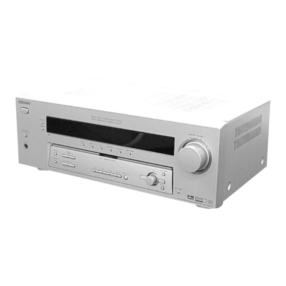
Sony STR-K850P Service Manual
Hide thumbs
Also See for STR-K850P:
- Operating instructions manual (52 pages) ,
- Limited warranty (1 page)
Table of Contents
Advertisement
SERVICE MANUAL
Ver 1.0 2003. 06
• STR-K850P is the tuner and the amplifier
section in HT-6600DP.
Dolby Laboratories Licensing Corporation.
"DOLBY" the double-D symbol ; "AC-3" and "PRO LOGIC"
are trademarks of Dolby Laboratories Licensing Corporation.
POWER OUTPUT AND TOTAL
HARMONIC DISTORTION:
With 8 ohm loads, both channels driven, from
40 – 20,000 Hz; rated 110 watts per channel
minimum RMS power, with no more than
0.7 % total harmonic distortion from 250
milliwatts to rated output (Models of area code
U only).
Amplifier section
POWER OUTPUT
Rated Power Output at Stereo Mode
(8 ohms 40 Hz – 20 kHz, THD 0.7 %)
110 W + 110 W
Reference Power Output
(8 ohms 1 kHz, THD 0.7 %)
FRONT
1)
:120 W/ch
1)
CENTER
: 120 W
1)
SURR
: 120 W/ch
1) Depending on the sound field settings and the
source, there may be no sound output.
Frequency response
MULTI CH IN,
CD/SACD, MD/TAPE,
DVD, VIDEO 1, 2
Inputs (Analog)
MULTI CH IN,
CD/SACD, MD/TAPE,
DVD, VIDEO 1, 2
Sony Corporation
9-877-410-01
2003F1678-1
Home Audio Company
© 2003.06
Published by Sony Engineering Corporation
STR-K850P
SPECIFICATIONS
2) INPUT SHORT (with sound field and tone
bypassed).
3) Weighted network, input level.
Inputs (Digital)
DVD (Coaxial)
VIDEO 2, CD/SACD,
MD/TAPE (Optical)
Outputs
MD/TAPE (OUT),
VIDEO 1
(AUDIO OUT)
SUB WOOFER
Outputs (Digital)
MD/TAPE (Option)
10 Hz – 70 kHz
Tone
+0.5/–2 dB (with sound
Gain levels:
field and tone bypassed)
Sensitivity: 500 mV
Impedance: 50 kilohms
S/N
2)
: 96 dB
3)
(A, 500 mV
)
Canadian Model
Sensitivity: –
Impedance: 75 ohms
S/N: 100 dB
(A, 20 kHz LPF)
Sensitivity: –
Impedance: –
S/N: 100 dB
(A, 20 kHz LPF)
Voltage: 500 mV
Impedance: 10 kilohms
Voltage: 2 V
Impedance: 1 kilohms
Sensitivity: –
±6 dB, 1 dB step
FM STEREO FM-AM RECEIVER
US Model
— Continued on next page —
Advertisement
Table of Contents

Related Manuals for Sony STR-K850P


Summary of Contents for Sony STR-K850P
- Page 1 SERVICE MANUAL US Model Canadian Model Ver 1.0 2003. 06 • STR-K850P is the tuner and the amplifier section in HT-6600DP. Dolby Laboratories Licensing Corporation. “DOLBY” the double-D symbol ; “AC-3” and “PRO LOGIC” are trademarks of Dolby Laboratories Licensing Corporation.
- Page 2 STR-K850P FM tuner section Harmonic distortion 0.5 % (50 mV/m, 400 Hz) Tuning range 87.5 - 108.0 MHz Selectivity At 9 kHz: 35 dB Antenna terminals 75 ohms, unbalanced At 10 kHz: 40 dB Intermediate Frequency 10.7 MHz 4) You can change the AM tuning scale to 9 kHz or 10 kHz.
- Page 3 CRITIQUES POUR LA SÉCURITÉ DE FONCTIONNEMENT. NE COMPONENTS WITH SONY PARTS WHOSE PART NUMBERS REMPLACER CES COMPOSANTS QUE PAR DES PIÈSES SONY APPEAR AS SHOWN IN THIS MANUAL OR IN SUPPLEMENTS DONT LES NUMÉROS SONT DONNÉS DANS CE MANUEL OU PUBLISHED BY SONY.
-
Page 4: Table Of Contents
STR-K850P MODEL IDENTIFICATION TABLE OF CONTENTS — BACK PANEL — 1. GENERAL ·········································································· 5 2. TEST MODE ······································································ 6 3. DIAGRAMS 3-1. Circuit Board Location ················································· 7 3-2. Block Diagrams – MAIN Section – ····························· 8 – DIGITAL/POWER Section – ···································· 9 3-3. -
Page 5: General
STR-K850P SECTION 1 GENERAL This section is extracted from instruction manual. MD/TAPE 9 (22) ALPHABETICAL ORDER NUMBERS AND SYMBOLS MEMORY wj (31) MOVIE (button/indicator) ws (25, 2CH (button/indicator) wf (24, A – H 26, 29) A.F.D. (button/indicator) wd MULTI CHANNEL DECODING ?/1 (power) 1 (16, 21, 29, 35, (24–26) -
Page 6: Test Mode
STR-K850P SECTION 2 TEST MODE 4. Press the VIDEO1 button, All segments and all LEDS turn off. FACTORY PRESET MODE * All preset contents are reset to the default setting. 5. Every pressing of the VIDEO1 button turns on each segment * Procedure: and LED one after another in the same order. -
Page 7: Diagrams
STR-K850P SECTION 3 DIAGRAMS 3-1. Circuit Board Location THIS NOTE IS COMMON FOR PRINTED WIRING For printed wiring boards. Note: BOARDS AND SCHEMATIC DIAGRAMS. • X : parts extracted from the component side. (In addition to this necessary note is printed in each •... -
Page 8: Block Diagrams - Main Section
STR-K850P 3-2. Block Diagrams – MAIN Section – IC201 ANALOG SOUND TUNER PACK PROCESSOR 75 Ω L CH INL1 IC1601(1/3) COAXIAL R CH R-CH SYSTEM CONTROL. ANTENNA ST-DO J402 ST-DI L OUT CD/SACD INL3 Q361 SLATCH MUTING RECL2 STEREO STEREO... -
Page 9: Digital/Power Section
STR-K850P – DIGITAL/POWER Section – R-CH J791 IC701 PHONES POWER AMP RY791 Q790 Q703 +V OUT2 RELAY BOOSTER DRIVE Q701,702 LIMITER TM602 RY701 • R-CH is omitted due to same as L-CH FRONT A Q740 D731 Q710 • Signal Path... -
Page 10: Digital Board (Side A)
STR-K850P 3-3. Printed Wiring Board – DIGITAL Board (SIDE A) – • See page 7 for Circuit Boards Location. • : Uses unleaded solder. R1120 IC1103 • Semiconductor Location R1122 IC1101 Ref. No. Location IC1202 D1101 D1601 IC1101 IC1102 IC1103... -
Page 11: Digital Board (Side B)
STR-K850P 3-4. Printed Wiring Board – DIGITAL Board (SIDE B) – • See page 7 for Circuit Boards Location. • : Uses unleaded solder. ANTENNA FM 75Ω VIDEO COAXIAL MAIN BOARD BOARD CNS250 CNP911 TUNER (Page 21) (Page 14) PACK... -
Page 12: Schematic Diagram - Digital Section (1/2)
STR-K850P 3-5. Schematic Diagram – DIGITAL Section (1/2) – • See page 7 for Waveforms. • See page 23 for IC Block Diagrams. C1127 C1126 C1129 IC1104 0.001 TORX141L C1111 R1120 C1120 C1112 R1115 0.01 IC1105 TORX141L R1121 R1364 JR1116... -
Page 13: Schematic Diagram - Digital Section (2/2)
STR-K850P 3-6. Schematic Diagram – DIGITAL Section (2/2) – • See page 7 for Waveforms. C1617 0.01 C1905 CNP5 IC1602 S-80929CNMC -G8ZT2G C1913 R1642 C1906 470 16V C1612 IC1902 M5F7810L C1908 470 16V CNS4 C1914 CNP6 47 16V IC1903 FB1603... -
Page 14: Printed Wiring Board - Main Section
STR-K850P 3-7. Printed Wiring Board – MAIN Section – • See page 7 for Circuit Boards Location. • : Uses unleaded solder. J401 CD/SACD MULTI CH IN SPEAKERS FRONT SURROUND CENTER FRONT B FRONT A WOOFER VIDEO BOARD CNP156 (Page 21) -
Page 15: Schematic Diagram - Main Section (1/3)
STR-K850P 3-8. Schematic Diagram – MAIN Section (1/3) – • See page 23 for IC Block Diagrams. C407 J404 2.2 50V R373 Q361 2SC3576-AC R407 C492 C484 C494 R361 4.7 50V 4.7 50V R363 4.7k C457 R457 C491 100k 2.2 50V... -
Page 16: Schematic Diagram - Main Section (2/3)
STR-K850P 3-9. Schematic Diagram – MAIN Section (2/3) – • See page 24 for IC Block Diagrams. Q747 BN1F4M-TP IC701 CNP791 R742 CN792 R792 C717 R719 C720 Q740 4.7k 220p 2SC1815 GR-TPE2 Q701 Q705 J791 R714 2SA1115TP-EF Q748 2SA988TP C742... -
Page 17: Schematic Diagram - Main Section (3/3)
STR-K850P 3-10. Schematic Diagram – MAIN Section (3/3) – Q379 BN1F4M-TP R381 CN505 T901 CNP802 Q801 2SB734 -T-34 CNP501 C471 C822 R803 D804 D802 R474 RD5.6F-T7B2 D5SBA20-4003 RY803 C498 C805 CN801 R473 0.22 4.7k C803 R804 100V 6800 5.6k C801... -
Page 18: Printed Wiring Board - Power Section
STR-K850P 3-11. Printed Wiring Board – POWER Section – • See page 7 for Circuit Boards Location. • : Uses unleaded solder. MAIN BOARD CN792 (Page 14) PHONES • Semiconductor DIGITAL BOARD Location CNP5 Ref. No. Location (Page 11) D818... -
Page 19: Printed Wiring Board - Front Section
STR-K850P 3-12. Printed Wiring Board – FRONT Section – • See page 7 for Circuit Boards Location. • : Uses unleaded solder. DIGITAL BOARD CNS4 (Page 11) VOLUME BOARD • Semiconductor Location Ref. No. Location D101 D102 D103 D104 D105... -
Page 20: Schematic Diagram - Front Section
STR-K850P 3-13. Schematic Diagram – FRONT Section – C109 C108 R199 R198 FL101 FLUORESCENT INDICATOR TUBE R160 R175 R162 D101 SEL5E20CTP15 C101 C104 D105 D104 D103 D102 SEL5821A-TP15 SEL5821A-TP15 SEL5821A-TP15 SEL5821A-TP15 Q100 2SC2785TP-HFE LED DRIVER R141 2.2k C144 R101 R102... -
Page 21: Printed Wiring Board - Video Section
STR-K850P 3-14. Printed Wiring Board – VIDEO Section – • : Uses unleaded solder. MONITOR VIDEO 2 MONITOR /R-Y /B-Y /R-Y /B-Y /R-Y /B-Y J301 VIDEO 1 VIDEO 2 MONITOR S-VIDEO IN S-VIDEO OUT S-VIDEO IN S-VIDEO IN S-VIDEO OUT... -
Page 22: Schematic Diagram - Video Section
STR-K850P 3-15. Schematic Diagram – VIDEO Section – • See page 24 for IC Block Diagrams. C315 C210 C214 IC807 J201 R220 CNP156 EH 3P C827 C208 C824 R201 IC804 NJM79M05FA C825 C200 J200 C809 R200 C206 C207 R221 R218... -
Page 23: Ic Block Diagrams
STR-K850P 3-16. IC Block Diagrams IC1101 LC89056W-E (DIGITAL BOARD) AUDIO C BIT PA/PB DETECT DETECT EMPHA SAMPLING FREQUENCY MICROCOMPUTER INTERFACE XSEL LOCK XOUT CLOCK DETECT XMCK 19 DVDD MODE0 MODE 18 DGND SELECT MODE1 XSTATE DGND DATAO DVDD LRCK DOSEL0... - Page 24 STR-K850P IC701, IC702 µPC2581V-S (MAIN BOARD) IC501 STK350-230 (MAIN BOARD) BIAS CIRCUIT PROTECTOR INPUT REG DRIVE DRIVE DRIVE DRIVE 2 3 4 5 6 8 9 10 11 12 13 14 15 -VEOUT +VEOUT IC203 NJM2595D (VIDEO BOARD) IC251, IC252 NJM2595D (S-VIDEO BOARD) M.OUT...
-
Page 25: Ic Pin Function Descriptions
STR-K850P 3-17. IC Pin Function Descriptions • IC1601 MB90478PF-G-152-BND (SYSTEM CONTROL) Pin No. Pin Name Description DATAO Audio data signal input from DIR GP9 signal input from DSP BST signal output to DSP HCS signal output to DSP HACN HACN signal input from DSP... - Page 26 STR-K850P Pin No. Pin Name Description Operation mode setting input RDS CLOCK RDS clock signal input (Not used) RDS DATA RDS data signal input (Not used) SIRCS Data signal input from the remote control sensor FUSE DETECT Fuse detect signal input...
-
Page 27: Exploded Views
STR-K850P SECTION 4 EXPLODED VIEWS NOTE: • -XX, -X mean standardized parts, so they may • The mechanical parts with no reference number The components identified by mark 0 or have some differences from the original one. in the exploded views are not supplied. -
Page 28: Chassis Section
STR-K850P 4-2. Chassis Section not supplied Q754 Q653 Q603 Q753 Q704 Q604 Q654 not supplied 55 67 Q703 Q504 Q503 T901 supplied not supplied F901 supplied supplied supplied supplied not supplied supplied Ref. No. Part No. Description Remarks Ref. No. -
Page 29: Electrical Parts List
STR-K850P SECTION 5 BRIDGEABLE DIGITAL ELECTRICAL PARTS LIST NOTE: • Due to standardization, replacements in the • RESISTORS • Abbreviation parts list may be different from the parts All resistors are in ohms. CND : Canaian model specified in the diagrams or the components... - Page 30 STR-K850P DIGITAL Ref. No. Part No. Description Remarks Ref. No. Part No. Description Remarks C1504 1-126-964-11 ELECT 10uF 20.00% 50V C1914 1-126-947-11 ELECT 47uF 20.00% 16V C1505 1-164-156-11 CERAMIC CHIP 0.1uF < CONNECTOR > C1506 1-126-935-11 ELECT 470uF 20.00% 16V...
- Page 31 STR-K850P DIGITAL Ref. No. Part No. Description Remarks Ref. No. Part No. Description Remarks < JUMPER RESISTOR > R1220 1-216-813-11 METAL CHIP 1/16W R1221 1-216-813-11 METAL CHIP 1/16W JR1112 1-216-864-11 METAL CHIP 1/16W R1222 1-216-813-11 METAL CHIP 1/16W JR1113 1-216-864-11 METAL CHIP...
- Page 32 STR-K850P DIGITAL DISPLAY Ref. No. Part No. Description Remarks Ref. No. Part No. Description Remarks R1607 1-216-821-11 METAL CHIP 1/16W R1671 1-216-833-11 METAL CHIP 1/16W R1608 1-216-821-11 METAL CHIP 1/16W R1672 1-216-841-11 METAL CHIP 1/16W R1609 1-216-821-11 METAL CHIP 1/16W...
- Page 33 STR-K850P DISPLAY HEADPHONE Ref. No. Part No. Description Remarks Ref. No. Part No. Description Remarks C140 1-128-813-11 CERAMIC 220PF R135 1-249-429-11 CARBON 1/4W C141 1-128-813-11 CERAMIC 220PF R136 1-249-433-11 CARBON 1/4W C142 1-128-813-11 CERAMIC 220PF R141 1-249-421-11 CARBON 2.2K 1/4W F...
- Page 34 STR-K850P MAIN Ref. No. Part No. Description Remarks Ref. No. Part No. Description Remarks A-4731-762-A MAIN BOARD, COMPLETE C492 1-126-963-11 ELECT 4.7uF 20.00% 50V C493 1-126-963-11 ELECT 4.7uF 20.00% 50V ********************* C494 1-126-963-11 ELECT 4.7uF 20.00% 50V 7-685-646-79 SCREW +BVTP 3X8 TYPE2 IT-3...
- Page 35 STR-K850P MAIN Ref. No. Part No. Description Remarks Ref. No. Part No. Description Remarks C717 1-162-815-11 CERAMIC 47PF 5.00% 500V D691 8-719-991-33 DIODE 1SS133T-72 C720 1-128-813-11 CERAMIC 220PF D705 8-719-991-33 DIODE 1SS133T-72 C721 1-126-934-11 ELECT 220uF 20.00% 16V D710 8-719-991-33 DIODE 1SS133T-72...
- Page 36 STR-K850P MAIN Ref. No. Part No. Description Remarks Ref. No. Part No. Description Remarks Q505 8-729-140-82 TRANSISTOR 2SA988TP-PAFAEA R381 1-249-429-11 CARBON 1/4W Q506 8-729-140-82 TRANSISTOR 2SA988TP-PAFAEA Q540 8-729-281-53 TRANSISTOR 2SC1815GR-TPE2 R402 1-249-417-11 CARBON 1/4W F Q550 8-729-119-79 TRANSISTOR 2SC2785TP-FEK R404...
- Page 37 STR-K850P MAIN Ref. No. Part No. Description Remarks Ref. No. Part No. Description Remarks R555 1-249-433-11 CARBON 1/4W R694 1-249-429-11 CARBON 1/4W R695 1-249-429-11 CARBON 1/4W R556 1-249-433-11 CARBON 1/4W R696 1-249-435-11 CARBON 1/4W R557 1-249-431-11 CARBON 1/4W R698 1-249-429-11 CARBON...
- Page 38 STR-K850P MAIN POWER STANDBY S-VIDEO Ref. No. Part No. Description Remarks Ref. No. Part No. Description Remarks R769 1-249-425-11 CARBON 4.7K 1/4W F < CONNECTOR > R770 1-249-437-11 CARBON 1/4W R771 1-247-850-11 CARBON 6.2K 1/4W CNP901 1-564-321-00 PIN, CONNECTOR (3.96mm PITCH) 2P...
- Page 39 STR-K850P S-VIDEO VIDEO Ref. No. Part No. Description Remarks Ref. No. Part No. Description Remarks C252 1-164-159-11 CERAMIC 0.1uF C214 1-164-159-11 CERAMIC 0.1uF C253 1-164-159-11 CERAMIC 0.1uF C215 1-164-159-11 CERAMIC 0.1uF C254 1-126-947-11 ELECT 47uF 20.00% 25V C248 1-164-159-11 CERAMIC 0.1uF...
- Page 40 STR-K850P VIDEO VOLUME Ref. No. Part No. Description Remarks Ref. No. Part No. Description Remarks R306 1-247-804-11 CARBON 1/4W R307 1-247-804-11 CARBON 1/4W R308 1-247-804-11 CARBON 1/4W R309 1-247-804-11 CARBON 1/4W R310 1-249-417-11 CARBON 1/4W F R311 1-249-417-11 CARBON 1/4W F...
- Page 41 STR-K850P MEMO...
- Page 42 STR-K850P REVISION HISTORY Clicking the version allows you to jump to the revised page. Also, clicking the version at the upper right on the revised page allows you to jump to the next revised page. Ver. Date Description of Revision...
Need help?
Do you have a question about the STR-K850P and is the answer not in the manual?
Questions and answers