Yamaha RX-V371 Series Service Manual
Hide thumbs
Also See for RX-V371 Series:
- Owner's manual (88 pages) ,
- Quick reference manual (9 pages) ,
- Quick reference manual (9 pages)
Table of Contents
Advertisement
Quick Links
RX-V371/HTR-3064
When the following parts are replaced, the model name and the destination MUST be written to the back-up IC
(EEPROM: IC222 on DIGITAL P.C.B.) to have proper operation. (See No. 22 SOFT SWITCH menu of the self-
diagnostic function.)
•
DIGITAL P.C.B.
•
EEPROM: IC222 on DIGITAL P.C.B.
This manual has been provided for the use of authorized YAMAHA Retailers and their service personnel.
It has been assumed that basic service procedures inherent to the industry, and more specifi cally YAMAHA Products, are already known
and understood by the users, and have therefore not been restated.
WARNING:
IMPORTANT:
The data provided is believed to be accurate and applicable to the unit(s) indicated on the cover. The research, engineering, and service
departments of YAMAHA are continually striving to improve YAMAHA products. Modifications are, therefore, inevitable and
specifi cations are subject to change without notice or obligation to retrofi t. Should any discrepancy appear to exist, please contact the
distributor's Service Division.
WARNING:
IMPORTANT:
■ CONTENTS
TO SERVICE PERSONNEL ............................................2
FRONT PANELS .........................................................3–4
REAR PANELS ...........................................................5–9
REMOTE CONTROL PANELS ..................................... 10
SPECIFICATIONS ................................................... 11–15
INTERNAL VIEW .......................................................... 16
SERVICE PRECAUTIONS ............................................ 16
DISASSEMBLY PROCEDURES ............................. 17–19
UPDATING FIRMWARE ..........................................20–22
SELF-DIAGNOSTIC FUNCTION ...........................23–46
1 0 1 2 0 6
SERVICE MANUAL
IMPORTANT NOTICE
Failure to follow appropriate service and safety procedures when servicing this product may result in personal injury,
destruction of expensive components, and failure of the product to perform as specifi ed. For these reasons, we advise
all YAMAHA product owners that any service required should be performed by an authorized YAMAHA Retailer or
the appointed service representative.
The presentation or sale of this manual to any individual or fi rm does not constitute authorization, certifi cation or
recognition of any applicable technical capabilities, or establish a principle-agent relationship of any form.
Static discharges can destroy expensive components. Discharge any static electricity your body may have
accumulated by grounding yourself to the ground buss in the unit (heavy gauge black wires connect to this buss).
Turn the unit OFF during disassembly and part replacement. Recheck all work before you apply power to the unit.
DISPLAY DATA .......................................................47–48
IC DATA ...................................................................49–60
BLOCK DIAGRAM ........................................................61
PRINTED CIRCUIT BOARDS .................................62–75
PIN CONNECTION DIAGRAMS ................................... 76
SCHEMATIC DIAGRAMS .......................................77–85
REPLACEMENT PARTS LIST ................................87–95
REMOTE CONTROL ............................................. 96–100
ADVANCED SETUP ............................................ 101–102
Copyright © 2011
This manual is copyrighted by YAMAHA and may not be copied or
redistributed either in print or electronically without permission.
AV RECEIVER
All rights reserved.
P.O.Bo
, Hamamatsu, apan
'11.02
Advertisement
Table of Contents

Related Manuals for Yamaha RX-V371 Series


Summarization of Contents
IMPORTANT NOTICE
Critical Part Replacement Note
Model and destination must be written to back-up IC for specific part replacements.
SERVICE PERSONNEL GUIDELINES
Critical Component Handling
Information on replacing critical components with identical parts.
Leakage Current Measurement
Procedure for verifying insulation and measuring leakage current.
Chemical Safety Warning
Warning about chemicals in components and safety during soldering.
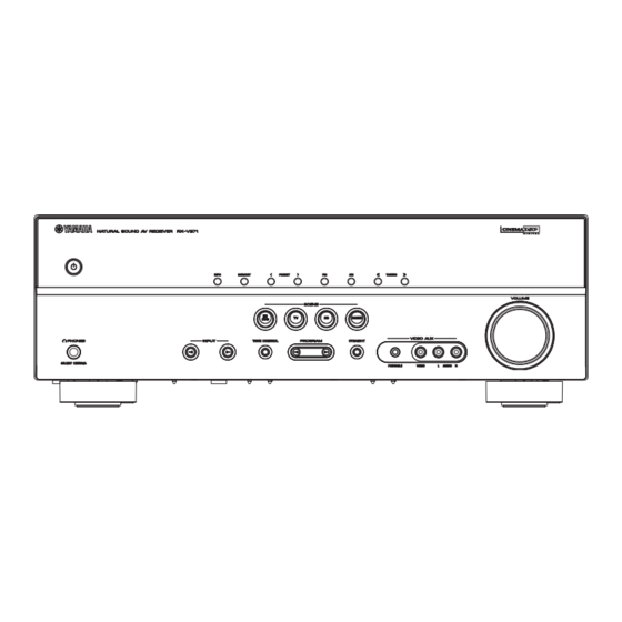
FRONT PANEL VIEWS
RX-V371 Front Panel (U, C, T)
Front panel layout for RX-V371 U, C, T models.
RX-V371 Front Panel (R, K, A, B, G, F, L, S)
Front panel layout for RX-V371 R, K, A, B, G, F, L, S models.
FRONT PANEL VIEWS (Continuing)
HTR-3064 Front Panel (U, C, T)
Front panel layout for HTR-3064 U, C, T models.
HTR-3064 Front Panel (R, K, A, G, F, L, S)
Front panel layout for HTR-3064 R, K, A, G, F, L, S models.
REAR PANEL CONFIGURATIONS
RX-V371 Rear Panels (U, C)
Rear panel layout for RX-V371 U, C models.
RX-V371 Rear Panels (R, S)
Rear panel layout for RX-V371 R, S models.
RX-V371 Rear Panels (T)
Rear panel layout for RX-V371 T model.
REAR PANEL CONFIGURATIONS (Continuing)
RX-V371 Rear Panels (K)
Rear panel layout for RX-V371 K model.
RX-V371 Rear Panels (A)
Rear panel layout for RX-V371 A model.
RX-V371 Rear Panels (B, G, F)
Rear panel layout for RX-V371 B, G, F models.
REAR PANEL CONFIGURATIONS (Continuing)
RX-V371 Rear Panels (L)
Rear panel layout for RX-V371 L model.
HTR-3064 Rear Panels (U, C)
Rear panel layout for HTR-3064 U, C models.
HTR-3064 Rear Panels (R, S)
Rear panel layout for HTR-3064 R, S models.
REAR PANEL CONFIGURATIONS (Continuing)
HTR-3064 Rear Panels (T)
Rear panel layout for HTR-3064 T model.
HTR-3064 Rear Panels (K)
Rear panel layout for HTR-3064 K model.
HTR-3064 Rear Panels (A)
Rear panel layout for HTR-3064 A model.
REAR PANEL CONFIGURATIONS (Continuing)
HTR-3064 Rear Panels (G, F)
Rear panel layout for HTR-3064 G, F models.
HTR-3064 Rear Panels (L)
Rear panel layout for HTR-3064 L model.
REMOTE CONTROL LAYOUTS
RAV331 Remote Control
Remote control layout for RAV331 models.
RAV332 Remote Control
Remote control layout for RAV332 T model.
RAV433 Remote Control
Remote control layout for RAV433 models.
SPECIFICATIONS OVERVIEW
Audio Section Specifications
Detailed audio specifications including output power, sensitivity, and distortion.
Video & FM/AM Specifications
Video, FM, and AM signal specifications and tuning ranges.
GENERAL SPECIFICATIONS
Physical Dimensions & Accessories
Physical dimensions and list of included accessories.
MENU SYSTEM - SOUND FIELDS
Sound Field Parameter Adjustments
Parameters for adjusting sound field settings in the menu.
MENU SYSTEM - ADVANCED SETTINGS
Speaker and Sound Setup Options
Settings for speaker configuration and audio adjustments.
HDMI and Function Setup
Settings for HDMI connectivity and general functions.
MENU SYSTEM - DSP AND MEMORY
DSP Parameter Configuration
DSP parameters for various sound programs and modes.
Memory Guard Function
Function to guard settings in memory.
INTERNAL VIEW AND SERVICE PRECAUTIONS
Internal Component Layout
Diagram showing internal component locations.
Critical Service Safety Measures
Safety measures to take before and during servicing to avoid hazards.
DISASSEMBLY PROCEDURES - BASIC STEPS
Top Cover Removal
Steps for removing the top cover of the unit.
Front Panel Unit Removal
Steps for removing the front panel unit.
DISASSEMBLY PROCEDURES - PCB REMOVAL
DIGITAL P.C.B. Removal
Steps for removing the DIGITAL P.C.B.
OPERATION (4) P.C.B. Removal
Steps for removing the OPERATION (4) P.C.B.
DISASSEMBLY PROCEDURES - PCB CHECKING
DIGITAL P.C.B. Checking
Instructions for checking the DIGITAL P.C.B. after removal.
MAIN (1) P.C.B. Checking
Instructions for checking the MAIN (1) P.C.B. after removal.
FIRMWARE UPDATING PROCESS
Firmware Version Confirmation
How to check firmware version and checksum using self-diagnostic function.
Back-up IC Initialization
Steps to initialize the back-up IC after firmware update.
Required Tools for Update
List of tools required for firmware updating.
FIRMWARE UPDATING PROCESS - CONNECTION
BD/DVD/CD Player Connection
How to connect the unit to a BD/DVD/CD player for firmware update.
FIRMWARE UPDATING PROCESS - OPERATION
Firmware Update Operation Steps
Detailed steps for performing the firmware update operation.
SELF-DIAGNOSTIC FUNCTION - MENU ITEMS
BYPASS and RAM THROUGH Functions
Menu items for checking analog bypass and DSP signal routes.
HDMI AUDIO and SPEAKER SET
Menu items for checking HDMI audio and speaker output settings.
MIC CHECK and FL/MONITOR CHECK
Menu items for microphone and display checks.
MANUAL TEST and A/D DATA CHECK
Menu items for manual testing and A/D data checks.
VIDEO CHECK
Menu item for checking the video control section.
SELF-DIAGNOSTIC FUNCTION - MENU ITEMS (Continuing)
DOCK and HDMI Information/Select
Menu items for dock connection and HDMI status.
PROTECTION HISTORY and SOFT SWITCH
Menu items for protection history and soft switch settings.
FACTORY PRESET and ROM VER/SUM/PORT
Menu items for factory preset and firmware/checksum verification.
SELF-DIAGNOSTIC FUNCTION - OPERATION MODES
Starting Self-Diagnostic Function
How to start the self-diagnostic function.
Protection Cancel Mode Start
How to start self-diagnostic with protection functions disabled.
Canceling Self-Diagnostic Function
Steps to cancel the self-diagnostic function and restore settings.
SELF-DIAGNOSTIC FUNCTION - DISPLAY MESSAGES
Normal Power Off Display
Display when the unit is turned off normally.
Protection Function Power Off Display
Displays when protection function caused power off.
Excess Current Protection Display
Display and cause for excess current protection.
SELF-DIAGNOSTIC FUNCTION - PROTECTION CAUSES
Speaker Terminal Short Protection
Display and cause for speaker terminal short protection.
Abnormal DC Output Protection
Display and cause for abnormal DC output protection.
Power Supply Voltage Abnormality Protection
Display and cause for power supply voltage abnormality protection.
SELF-DIAGNOSTIC FUNCTION - TEMPERATURE PROTECTION
Excessive Heatsink Temperature Protection
Display and cause for excessive heatsink temperature protection.
Protection Function History
How protection function history is stored and initialized.
SELF-DIAGNOSTIC FUNCTION - MENU NAVIGATION
Main and Sub-Menu Operation
How to navigate main and sub-menus in self-diagnostic mode.
Available Functions in Diagnostic Mode
Available functions in self-diagnostic mode besides menu items.
Initial Settings for Diagnostic Mode
Default settings when entering self-diagnostic mode.
SELF-DIAGNOSTIC FUNCTION - DETAILED MENUS
BYPASS Function Details
Details of the BYPASS menu for checking audio signal route.
ANALOG BYPASS Specifics
Specifics of the ANALOG BYPASS function and its signal path.
SELF-DIAGNOSTIC FUNCTION - DETAILED MENUS (Continuing)
RAM THROUGH Function Details
Details of the RAM THROUGH menu for checking audio signal via DSP.
RAM MARGIN, FULL ALL, CENTER Details
Specifics of RAM MARGIN, FULL ALL, and CENTER functions.
SELF-DIAGNOSTIC FUNCTION - DETAILED MENUS (Continuing)
RAM FULL SURROUND Details
Specifics of the RAM FULL SURROUND function.
RAM FULL SURROUND BACK
RAM FULL SURROUND BACK (not for service).
SELF-DIAGNOSTIC FUNCTION - DETAILED MENUS (Continuing)
HDMI AUDIO and SPEAKER SET Details
Details of HDMI AUDIO and SPEAKER SET menus.
SELF-DIAGNOSTIC FUNCTION - DETAILED MENUS (Continuing)
Speaker Setting Options (FRONT, CENTER, LFE/BASS, TONE)
Details for FRONT, CENTER, LFE/BASS, and TONE speaker settings.
SPEAKER 6 ohms Setting
Details for SPEAKER 6 ohms setting (not for service).
SELF-DIAGNOSTIC FUNCTION - DETAILED MENUS (Continuing)
LIMITER CONTROL and MIC CHECK Details
Details of LIMITER CONTROL and MIC CHECK functions.
SELF-DIAGNOSTIC FUNCTION - DETAILED MENUS (Continuing)
FL/MONITOR CHECK Details
Details of FL/MONITOR CHECK function.
FL/Monitor Check Sub-options
Sub-options for FL/Monitor check: Initial Display, All Segments, Dimmer, Pattern.
SELF-DIAGNOSTIC FUNCTION - DETAILED MENUS (Continuing)
MANUAL TEST and A/D DATA CHECK Details
Details of MANUAL TEST and A/D DATA CHECK functions.
PS/DC and TH1/TH2 Protection Checks
Check for power supply voltage, DC output, and heatsink temperature.
SELF-DIAGNOSTIC FUNCTION - DETAILED MENUS (Continuing)
AMP/DK and K1/K2 Checks
Check amplifier output level, DOCK type, and panel keys.
SELF-DIAGNOSTIC FUNCTION - DETAILED MENUS (Continuing)
VIDEO CHECK and I2C Check
Details of VIDEO CHECK and I2C bus connection checks.
SELF-DIAGNOSTIC FUNCTION - DETAILED MENUS (Continuing)
DOCK and Bluetooth Version Check
Details of DOCK jack and Bluetooth version checks.
SELF-DIAGNOSTIC FUNCTION - DETAILED MENUS (Continuing)
HDMI Information and Select Checks
Details of HDMI module information and input signal checks.
SELF-DIAGNOSTIC FUNCTION - DETAILED MENUS (Continuing)
IF STATUS and BUS CHECK Details
Details of input status and bus communication checks.
SELF-DIAGNOSTIC FUNCTION - DETAILED MENUS (Continuing)
PROTECTION HISTORY Details
Display protection function history.
SELF-DIAGNOSTIC FUNCTION - SOFT SWITCH SETTINGS
Switch Mode Selection
Selects mode for writing model name/destination.
Model and Destination Selection
Selects the model name and destination.
SELF-DIAGNOSTIC FUNCTION - PRESET SETTINGS
UPDATE TI Function
Update TI function (not for service).
FACTORY PRESET Options
Reserve or inhibit initialization of the back-up IC.
PRESET INHIBIT vs RESERVED
Inhibits or reserves back-up IC initialization.
SELF-DIAGNOSTIC FUNCTION - FIRMWARE INFO
ROM VER/SUM/PORT Details
Displays firmware version, checksums, model, and destination.
MODEL/DESTINATION and VERIFY
Displays model/destination and verify function (not for service).
DISPLAY DATA - PINOUT AND GRID
V1001 Pin Connections
Pin connection diagram for V1001 connector.
Segment Grid Assignments
Grid assignment for display segments.
DISPLAY DATA - ANODE CONNECTIONS
Segment Anode Connections
Anode connection details for display segments.
IC DATA - MAIN P.C.B. COMPONENTS
IC21: R2A15220FP Details
Data for IC21, an 8-channel electronic volume IC.
IC DATA - DIGITAL P.C.B. COMPONENTS
IC241: D70YE101BRFP266 Details
Data for IC241, a decoder/post processor.
IC DATA - DIGITAL P.C.B. COMPONENTS (Continuing)
IC221: R5F364AMNFB Details
Data for IC221, a microprocessor.
BLOCK DIAGRAMS OVERVIEW
Digital Section Block Diagram
Block diagram of the digital section.
Main and Operation Sections Block Diagrams
Block diagrams of the main audio and operation sections.
PRINTED CIRCUIT BOARD LAYOUTS - DIGITAL & MAIN
DIGITAL (Side A) PCB Layout
Printed circuit board layout for the DIGITAL section (Side A).
MAIN (1) (Side A) PCB Layout
Printed circuit board layout for MAIN (1) (Side A).
AM/FM Tuner PCB Layout
Printed circuit board layout for the AM/FM TUNER.
PRINTED CIRCUIT BOARD LAYOUTS - DIGITAL (Continuing)
DIGITAL (Side B) PCB Layout
Printed circuit board layout for the DIGITAL section (Side B).
PRINTED CIRCUIT BOARD LAYOUTS - OPERATION
OPERATION (1) (Side A) PCB Layout
Printed circuit board layout for OPERATION (1) (Side A).
OPERATION (4) (Side A) PCB Layout
Printed circuit board layout for OPERATION (4) (Side A).
OPERATION (5) (Side A) PCB Layout
Printed circuit board layout for OPERATION (5) (Side A).
OPERATION (6) (Side A) PCB Layout
Printed circuit board layout for OPERATION (6) (Side A).
PRINTED CIRCUIT BOARD LAYOUTS - OPERATION (Continuing)
OPERATION (1) (Side B) PCB Layout
Printed circuit board layout for OPERATION (1) (Side B).
OPERATION (4) (Side B) PCB Layout
Printed circuit board layout for OPERATION (4) (Side B).
OPERATION (5) (Side B) PCB Layout
Printed circuit board layout for OPERATION (5) (Side B).
OPERATION (6) (Side B) PCB Layout
Printed circuit board layout for OPERATION (6) (Side B).
PRINTED CIRCUIT BOARD LAYOUTS - OPERATION (Continuing)
OPERATION (2) (Side A) PCB Layout
Printed circuit board layout for OPERATION (2) (Side A).
OPERATION (3) (Side A) PCB Layout
Printed circuit board layout for OPERATION (3) (Side A).
PRINTED CIRCUIT BOARD LAYOUTS - OPERATION (Continuing)
OPERATION (2) (Side B) PCB Layout
Printed circuit board layout for OPERATION (2) (Side B).
OPERATION (3) (Side B) PCB Layout
Printed circuit board layout for OPERATION (3) (Side B).
PRINTED CIRCUIT BOARD LAYOUTS - OPERATION (Continuing)
OPERATION (4) (Side A) PCB Layout
Printed circuit board layout for OPERATION (4) (Side A).
OPERATION (5) (Side A) PCB Layout
Printed circuit board layout for OPERATION (5) (Side A).
OPERATION (6) (Side A) PCB Layout
Printed circuit board layout for OPERATION (6) (Side A).
PRINTED CIRCUIT BOARD LAYOUTS - OPERATION (Continuing)
OPERATION (4) (Side B) PCB Layout
Printed circuit board layout for OPERATION (4) (Side B).
OPERATION (5) (Side B) PCB Layout
Printed circuit board layout for OPERATION (5) (Side B).
OPERATION (6) (Side B) PCB Layout
Printed circuit board layout for OPERATION (6) (Side B).
PRINTED CIRCUIT BOARD LAYOUTS - OPERATION (Continuing)
OPERATION (7) (Side A) PCB Layout
Printed circuit board layout for OPERATION (7) (Side A).
OPERATION (8) (Side A) PCB Layout
Printed circuit board layout for OPERATION (8) (Side A).
OPERATION (9) (Side A) PCB Layout
Printed circuit board layout for OPERATION (9) (Side A).
PRINTED CIRCUIT BOARD LAYOUTS - OPERATION (Continuing)
OPERATION (7) (Side B) PCB Layout
Printed circuit board layout for OPERATION (7) (Side B).
OPERATION (8) (Side B) PCB Layout
Printed circuit board layout for OPERATION (8) (Side B).
OPERATION (9) (Side B) PCB Layout
Printed circuit board layout for OPERATION (9) (Side B).
PRINTED CIRCUIT BOARD LAYOUTS - MAIN
MAIN (1) (Side A) PCB Layout
Printed circuit board layout for MAIN (1) (Side A).
PRINTED CIRCUIT BOARD LAYOUTS - MAIN (Continuing)
MAIN (1) (Side B) PCB Layout
Printed circuit board layout for MAIN (1) (Side B).
PRINTED CIRCUIT BOARD LAYOUTS - MAIN (Continuing)
MAIN (2) (Side A) PCB Layout
Printed circuit board layout for MAIN (2) (Side A).
MAIN (3) (Side A) PCB Layout
Printed circuit board layout for MAIN (3) (Side A).
MAIN (4) (Side A) PCB Layout
Printed circuit board layout for MAIN (4) (Side A).
PRINTED CIRCUIT BOARD LAYOUTS - MAIN (Continuing)
MAIN (2) (Side B) PCB Layout
Printed circuit board layout for MAIN (2) (Side B).
MAIN (3) (Side B) PCB Layout
Printed circuit board layout for MAIN (3) (Side B).
MAIN (4) (Side B) PCB Layout
Printed circuit board layout for MAIN (4) (Side B).
COMPONENT PIN CONNECTION DIAGRAMS
IC Pin Connections
Pin connection diagrams for various IC components.
Diode Pin Connections
Pin connection diagrams for various diode components.
Transistor Pin Connections
Pin connection diagrams for various transistor components.
SCHEMATIC DIAGRAMS - DIGITAL SECTION
Digital Section Diagram (1/4)
Schematic diagram for the DIGITAL section (part 1/4).
SCHEMATIC DIAGRAMS - DIGITAL SECTION (Continuing)
Digital Section Diagram (2/4)
Schematic diagram for the DIGITAL section (part 2/4).
SCHEMATIC DIAGRAMS - DIGITAL SECTION (Continuing)
Digital Section Diagram (3/4)
Schematic diagram for the DIGITAL section (part 3/4).
SCHEMATIC DIAGRAMS - DIGITAL SECTION (Continuing)
Digital Section Diagram (4/4)
Schematic diagram for the DIGITAL section (part 4/4).
SCHEMATIC DIAGRAMS - OPERATION SECTION
Operation Section Diagram (1/2)
Schematic diagram for the OPERATION section (part 1/2).
SCHEMATIC DIAGRAMS - OPERATION SECTION (Continuing)
Operation Section Diagram (2/2)
Schematic diagram for the OPERATION section (part 2/2).
SCHEMATIC DIAGRAMS - MAIN SECTION
Main Section Diagram (1/3)
Schematic diagram for the MAIN section (part 1/3).
SCHEMATIC DIAGRAMS - MAIN SECTION (Continuing)
Main Section Diagram (2/3)
Schematic diagram for the MAIN section (part 2/3).
SCHEMATIC DIAGRAMS - MAIN SECTION (Continuing)
Main Section Diagram (3/3)
Schematic diagram for the MAIN section (part 3/3).
REPLACEMENT PARTS LIST - ELECTRICAL COMPONENTS
Electrical Component Parts List
List of electrical components with abbreviations and descriptions.
REPLACEMENT PARTS LIST - DIGITAL SECTION
Digital Section Parts List
Replacement parts list for the DIGITAL section.
REPLACEMENT PARTS LIST - DIGITAL & OPERATION
Digital and Operation Section Parts
Replacement parts for DIGITAL and OPERATION sections.
REPLACEMENT PARTS LIST - OPERATION & MAIN
Operation and Main Section Parts
Replacement parts for OPERATION and MAIN sections.
REPLACEMENT PARTS LIST - MAIN SECTION
Main Section Parts List
Replacement parts list for the MAIN section.
REPLACEMENT PARTS LIST - MAIN SECTION (Continuing)
Main Section Parts List
Replacement parts list for the MAIN section.
REPLACEMENT PARTS LIST - RESISTORS
Carbon Resistor Specifications
List of carbon resistors with values and part numbers.
OVERALL ASSEMBLY DIAGRAMS
Assembly Diagrams for Model Variants
Overall assembly diagrams for different model variants.
OVERALL ASSEMBLY DIAGRAMS - ACCESSORIES
Included Accessories List
List of accessories included with the unit.
REMOTE CONTROL DETAILS
Remote Control Diagrams and Schematics
Schematic diagrams and layouts for remote controls.
REMOTE CONTROL KEY CODES - AMP MODE
RAV331/RAV332 AMP Mode Key Codes
Key codes for RAV331/RAV332 in AMP MODE.
REMOTE CONTROL KEY CODES - SOURCE MODE 1/2
RAV331/RAV332 Source Mode 1/2 Key Codes
Key codes for RAV331/RAV332 in SOURCE MODE 1/2.
REMOTE CONTROL KEY CODES - SOURCE MODE 2/2
RAV331/RAV332 Source Mode 2/2 Key Codes
Key codes for RAV331/RAV332 in SOURCE MODE 2/2.
REMOTE CONTROL KEY CODES - RAV433
RAV433 Key Codes
Key codes for RAV433 remote control.
ADVANCED SETUP - U, C MODELS
U, C Model Advanced Setup Guide
Advanced setup guide for U, C models.
ADVANCED SETUP - OTHER MODELS & PROCEDURES
R, T, K, A, B, G, F, L, S Model Setup
Advanced setup guide for R, T, K, A, B, G, F, L, S models.
Avoiding Remote Signal Interference
Tips to avoid remote control signal interference with multiple receivers.
Changing Remote Control ID
Steps to change the remote control ID.
FM/AM Frequency Step Adjustment
How to change FM/AM frequency steps for specific models.
Initializing Unit Settings
How to initialize various settings on the unit.
ADVANCED SETUP - B, G, F MODELS
B, G, F Model Advanced Setup Guide
Advanced setup guide for B, G, F models.
Need help?
Do you have a question about the RX-V371 Series and is the answer not in the manual?
Questions and answers