Table of Contents
Advertisement
SERVICE MANUAL
Ver. 1.1 2008.08
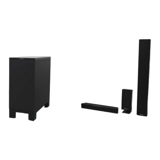
Photo: SA-WSF500
• SA-WFS200 is the active subwoofer in DAV-F200.
• SA-WFS500 is the active subwoofer in DAV-F500.
• SS-CTF500 is the center speaker in DAV-F500.
• SS-TSF200 is the front speaker in DAV-F200.
• SS-TSF500 is the front and Surround speaker in DAV-F500.
• SS-F500 is composed of four SS-TSF500, one SS-CTF500, four Speaker stands and Wall mounting brackets. (for DAV-F500)
Note:
• When SA-WSF200 is checked, it is necessary to connect it with HCD-F200.
• When SA-WSF500 is checked, it is necessary to connect it with HCD-F500.
Speakers
Front speaker (SS-TSF200)
Speaker system
2-Way 2-Driver speaker
system Bass reflex,
Magnetically Shielded
Speaker unit
Woofer: 65 mm cone type
Tweeter: 40 mm cone type
Rated impedance
3 ohms
Dimensions (approx.)
95 mm × 185 mm × 80 mm
(w/h/d)
95 mm × 215 mm × 105
mm (w/h/d) with stand
Mass (approx.)
0.85 kg
0.9 kg with stand
Subwoofer (SA-WSF200)
Amplifier Section
Power output (rated)
108 W + 108 W (at 3 ohms,
1 kHz, 1% THD)
RMS output power (reference)
FL/FR/C*: 141 W
(per channel at 3 ohms,
1 kHz, 10% THD)
Subwoofer*: 141 W (at 3
ohms, 80 Hz, 10% THD)
* Depending on the decoding mode settings and the
source, there may be no sound output.
Sony Corporation
9-889-149-02
2008H05-1
Audio&Video Business Group
©
2008.08
Published by Sony Techno Create Corporation
SS-CTF500/F500/TSF200/TSF500
Photo: SS-CTF500
Photo: SS-TSF200
SPECIFICATIONS
Power requirements:
Thai model:
220 V AC, 50/60 Hz
Other models:
220 V – 240 V AC, 50/60 Hz
Power consumption
On: 105 W
Standby: 0.3 W (at the
Power Saving mode)
Speaker system
Subwoofer Bass reflex
Speaker unit
160 mm cone type
Rated impedance
3 ohms
Dimensions (approx.)
205 mm × 460 mm × 475
mm (w/h/d)
Mass (approx.)
13 kg
Speakers
Front and Surround speaker (SS-TSF500)
Speaker system
2-Way 3-Driver speaker
system Bass reflex,
Magnetically Shielded
Speaker unit
Woofer: 65 mm cone type
× 2
Tweeter: 50 mm cone type
Rated impedance
3 ohms
Dimensions (approx.)
95 mm × 635 mm × 80 mm
(w/h/d)
305 mm × 1,205 mm × 305
mm (w/h/d) with stand
Mass (approx.)
1.8 kg
5.3 kg with stand
SA-WSF200/WSF500/
Canadian Model
Australian Model
Russian Model
SA-WSF500/SS-CTF500/F500/TSF500
Singapore Model
Photo: SS-TSF500
SS-CTF500/F500/TSF200/TSF500
Center speaker (SS-CTF500)
Speaker system
Speaker unit
Rated impedance
Dimensions (approx.)
Mass (approx.)
ACTIVE SUBWOOFER
SPEAKER SYSTEM
E Model
AEP Model
UK Model
SA-WSF200/SS-TSF200
Thai Model
SA-WSF200/WSF500/
Full range, Magnetically
Shielded
30 mm × 50 mm cone type
3 ohms
381 mm × 48 mm × 62 mm
(w/h/d)
0.5 kg
– Continued on next page –
SA-WSF200/WSF500
Advertisement
Table of Contents

Related Manuals for Sony SA-WSF500


Summarization of Contents
Specifications
Speaker System Specifications
Details of front, subwoofer, and surround speaker systems, units, dimensions, and mass.
Amplifier Section Specifications
Details of power output and RMS output power for the amplifier section.
Servicing Notes
Handling Unleaded Solder
Characteristics and handling guidelines for unleaded solder in electronics repair.
Optical Pick-Up Block Handling Precautions
Precautions for handling optical pick-up blocks and flexible boards to prevent damage.
Laser Diode Emission Check Safety
Safe procedure for checking laser diode emission to prevent eye damage.
Repair Preparation for SA-WSF Models
Essential preparation steps before servicing SA-WSF200 and SA-WSF500 units.
Model Identification and Part Numbers
Lists different models and their corresponding part numbers for identification.
Disassembly
Disassembly Flow Chart
Step-by-step flow chart guiding the disassembly process for the set.
Amplifier Complete Assembly Disassembly
Procedure for disassembling the amplifier assembly unit.
Loudspeaker Disassembly
Procedure for disassembling the loudspeaker unit (SP001).
Board Removal Procedures
Procedures for removing the back panel, speaker, and terminal boards.
Major Board Disassembly
Procedures for removing the AMP-DSP and Power boards.
Diagrams
Block Diagrams of Key Sections
Block diagrams illustrating DSP, AMP, and Power Supply sections.
Printed Wiring Board Layouts
Component layouts for AMP-DSP, SPEAKER, POWER, and REG boards.
Schematic Diagrams of Key Boards
Detailed schematic diagrams for AMP-DSP, SPEAKER, POWER, and REG boards.
Waveforms
AMP-DSP Board Waveforms
Visual representation of key signal waveforms on the AMP-DSP board.
IC Block Diagrams
IC Block Diagrams for AMP-DSP Board
Block diagrams illustrating the internal functions of ICs on the AMP-DSP board.
IC Pin Function Description
IC611 System Controller Pin Functions
Detailed pin functions for IC611, the system controller.
IC101 Main Board System Controller Pin Functions
Detailed pin functions for IC101, the main board system controller.
IC821 AMP-DSP Board DSP Pin Functions
Detailed pin functions for IC821, the DSP on the AMP-DSP board.
Exploded Views
Cabinet Section Exploded View
Exploded view illustrating the parts of the speaker cabinet assembly.
Amplifier Complete Assembly Exploded View
Exploded view of the amplifier assembly and its constituent parts.
Amplifier Board Section Exploded View
Exploded view detailing the amplifier board and its components.
Power Board Section Exploded View
Exploded view detailing the power board and its components.
Speaker Systems Exploded Views
Exploded views for SS-CTF500, TSF200, and TSF500 speaker models.
Speaker Stand Exploded View
Exploded view illustrating the parts of the speaker stand for SS-TSF500.
Electrical Parts List
Center Board Electrical Parts List
Comprehensive list of electrical parts for the center board.
Capacitor List
Detailed list of capacitors with part numbers, capacitance, tolerance, and voltage.
Connector List
List of connectors with part numbers and pin configurations.
DMB-FIT Board Electrical Parts List
List of electrical parts specific to the DMB-FIT board.
DMB-FIT Board Components
Further listing of electrical parts for the DMB-FIT board.
Need help?
Do you have a question about the SA-WSF500 and is the answer not in the manual?
Questions and answers