Table of Contents
Advertisement
Advertisement
Table of Contents

Related Manuals for Toyota 7FBEF 16


Summarization of Contents
General
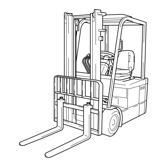
Vehicle Exterior Views
Shows front and rear views of the forklift.
Model Lineup
Lists models with payload, new/previous models, and voltage.
Development Objective
Development Objective
Explains the goals and concepts behind the new forklift models.
Features and Selling Points
Details major selling points like AC Motor Drive System.
Differences from Previous Models
Compares new models with previous ones across various specifications.
Electrical System
Battery Specifications
Details battery compartment dimensions and required weight.
Motors (Drive and Pump)
Covers drive motor specifications and features.
Main Controller
Explains the AC system controller and its functions.
Power Train
Drive Unit Structure
Details differences, general structure, and gears of the drive unit.
Traveling, Steering and Brake Systems
Accelerator Pedal System
Describes standard and optional accelerator pedals.
Tire Specifications
Lists standard tire settings and notes.
Steering System
Details the power steering system.
Brake System
Covers brake pedal and regenerative brake.
Instruments
Multiple Display Indicators
Explains the multiple display indicators and buttons.
Diagnosis and Error Codes
Explains how diagnosis is activated and lists error codes.
Mask Functions Overview
Describes mask functions for service staff, including Analyzer and Tuning.
Frame and Auxiliary Equipment
Body Frame Design
Details the frame structure, including front stay and side covers.
Auxiliary Equipment Details
Covers direction switch and lever.
Fuse Locations and Types
Lists fuse names, capacities, and locations.
Material Handling and Hydraulic System
V Mast Specifications
Describes the V mast, major improvements, and lost load center.
FSV Mast Specifications
Details the FSV mast, improvements, and lost load center.
Material Handling Speed Chart
Lists material handling speeds for different masts and models.
Oil Control Valve Function
Explains mast control valves, appearance, and specifications.
SAS Control System
SAS Configuration and Targets
Explains SAS concepts, targets, and system configuration.
Mast Control Functions
Lists functions like forward tilt angle control and backward tilt speed control.
Steering Synchronizer FHPS
Details the steering synchronizer system and its schematic.
Outline of Major Options
Fisherman Specification Details
Describes the fisherman specification for improved rust prevention.
Attachment List and Sideshifters
Lists available sideshifter attachments and their specifications.
Mini Lever Controls
Describes the mini lever structure and specifications.
Appendix
Major Vehicle Specifications
Lists major specifications for models 7FBEF15 and 7FBEF16.
Two-Plane Vehicle Drawings
Provides a two-plane drawing with dimension labels.
Electric Wiring Diagram
Shows the electric wiring diagram for vehicles with optional parts.
Need help?
Do you have a question about the 7FBEF 16 and is the answer not in the manual?
Questions and answers