Table of Contents
Advertisement
SERVICE MANUAL
Ver. 1.2 2011.06
• HBD-DZ340M/DZ640M/DZ840K/DZ840M/DZ940K are the
amplifi er, DVD/CD and tuner section in DAV-DZ340M/DZ640M/
DZ840K/DZ840M/DZ940K.
This system incorporates with Dolby* Digital and Dolby Pro Logic adaptive
matrix surround decoder and the DTS** Digital Surround System.
* Manufactured under license from Dolby Laboratories.
Dolby, Pro Logic, and the double-D symbol are trademarks of Dolby
Laboratories.
** Manufactured under license under U.S. Patent #'s:
5,451,942; 5,956,674; 5,974,380; 5,978,762; 6,487,535 & other U.S. and
worldwide patents issued & pending. DTS and DTS Digital Surround
are registered trademarks and the DTS logos and Symbol are trademarks
of DTS, Inc. © 1996-2008 DTS, Inc. All Rights Reserved.
Amplifi er Section
(DAV-DZ340M/DZ640M/DZ840M)
POWER OUTPUT (rated): Front L/Front R/Center/
Surround L/Surround R:
108 W (per channel at 3
ohms, 1 kHz, 1% THD)
POWER OUTPUT (reference):
Front L/Front R/Center/
Surround L/Surround R:
167 W (per channel at 3
ohms, 1 kHz)
Subwoofer: 165 W
(at 3 ohms, 80 Hz)
Inputs (Analog)
TV (AUDIO IN)
Sensitivity: 450/250 mV
MIC
Sensitivity: 1 mV
Inputs (Digital)
TV (Audio Return Channel/OPTICAL IN)
Input Stream: Dolby
Digital 5.1ch/DTS 5.1ch/
Linear PCM 2ch
(Sampling Frequency: less
than 48 kHz)
9-893-179-03
Sony Corporation
2011F04-1
©
2011.06
Published by Sony Techno Create Corporation
HBD-DZ340M/DZ640M/DZ840K/
Model Name Using Similar Mechanism
Mechanism Type
Optical Pick-up Name
SPECIFICATIONS
Amplifi er Section (DAV-DZ840K/DZ940K)
Brazilian models:
POWER OUTPUT:
Front L/Front R/Center/
Surround L/Surround R:
142 W (per channel at 3
ohms, 1 kHz, 10% THD*,
127 V)
Subwoofer: 140 W
(at 3 ohms, 80 Hz, 10%
THD*, 127 V)
* Total harmonic distortion
Other models:
POWER OUTPUT (rated): Front L/Front R/Center/
Surround L/Surround R:
108 W (per channel at 3
ohms, 1 kHz, 1% THD)
POWER OUTPUT (reference):
Front L/Front R/Center/
Surround L/Surround R:
167 W (per channel at 3
ohms, 1 kHz)
Subwoofer: 165 W (at 3
ohms, 80 Hz)
DZ840M/DZ940K
Russian Model
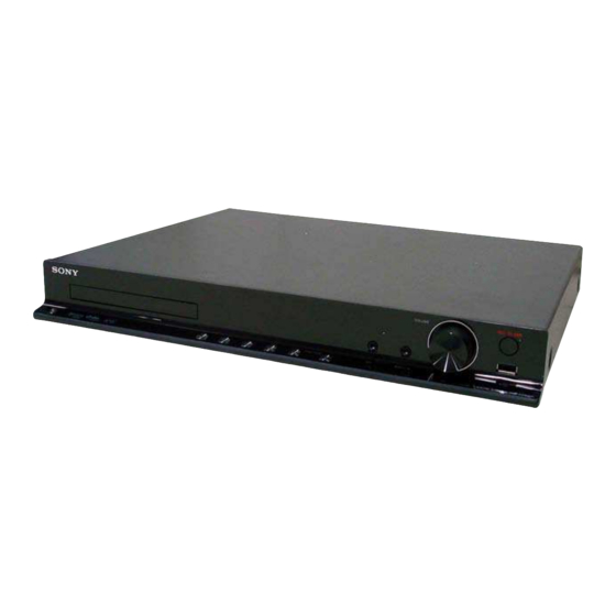
HBD-DZ340M/DZ640M/DZ840M
(Photo: HBD-DZ940K)
Inputs (Analog)
TV (AUDIO IN)
AUDIO IN
MIC
Inputs (Digital)
TV (Audio Return Channel/OPTICAL IN)
CD/DVD System
Laser Diode Properties
* This output is the value measurement at a distance
of 200 mm from the objective lens surface on the
Optical Pick-up Block with 7 mm aperture.
Signal format system
Latin American models:
Other models:
DVD RECEIVER
AEP Model
E Model
HBD-DZ840K/DZ940K
HBD-DZ340/DZ340K/
DZ640K/DZ740
CDM85MB-DVBU102
KHM-313CAA
Sensitivity: 450/250 mV
Sensitivity: 250/125 mV
Sensitivity: 1 mV
Input Stream: Dolby
Digital 5.1ch/DTS 5.1ch/
Linear PCM 2ch
(Sampling Frequency: less
than 48 kHz)
Emission Duration:
Continuous
Laser Output: Less than
44.6 PW
NTSC
NTSC/PAL
– Continued on next page –
Advertisement
Table of Contents

Related Manuals for Sony HBD-DZ840K


Summarization of Contents
General Specifications
Amplifier Section Details
Power output and input specifications for different amplifier models.
CD/DVD System Properties
Laser diode properties and signal format information.
System Specifications Details
USB, Tuner, Video, and General Specs
Covers USB file formats, tuner specs, video outputs, and general system info.
Safety and Handling Precautions
Component Handling Guidelines
Precautions for laser components, chip components, flexible circuits, and unleaded solder.
System Diagnostics and Version Information
Self-Diagnosis Function Usage
Interpreting service numbers for fault diagnosis.
Version Number Display Handling
Procedure for handling version number display on TV.
Servicing Notes
Optical Pick-up and Laser Diode Handling
Precautions for optical pick-up, laser emission, and disc tray lock.
Cleaning and Important Notices
Warnings about cleaning discs and potential screen damage.
Capacitor Discharge Safety
Power Board Capacitor Discharge
Procedure to discharge power board capacitors to prevent electric shock.
Disassembly Procedures Overview
Component Disassembly Sequence
Outline of disassembly steps starting with the unit's case.
Disassembly Procedures
Case Removal Steps
Detailed steps for removing the unit's case.
Disassembly Procedures
Loading Panel and Front Panel Removal
Steps to remove the loading panel and front panel assembly.
Disassembly Procedures
Key, Power Key, LED, Panel, and USB Boards Removal
Steps for removing key, power key, LED, panel, and USB boards.
Disassembly Procedures
ALC Board and Back Panel Removal
Steps for removing the ALC board and back panel.
Disassembly Procedures
Main Board and Power Board Removal
Steps for removing the main board and power board.
Disassembly Procedures
DVD Mechanism Deck and Tray Removal
Steps for removing the DVD mechanism deck and tray.
Disassembly Procedures
Belt Replacement and MS-203 Board Removal
Steps for belt replacement and MS-203 board removal.
Disassembly Procedures
Base Unit and Optical Pick-up Removal
Steps for base unit and optical pick-up removal.
Test Mode Operations
Cold Reset and Panel Test Modes
Procedures for cold reset and various panel test modes.
Disc Tray Lock and DVD Version Display
Functions for disc tray lock and DVD version display.
Product Out Mode Procedure
Steps for product out mode and RAM initialization.
Test Mode Operations
Color System and Tuner Display Tests
Procedures for color system change and tuner display mode.
Protection Factor Detection Tests
Identifying protection states like SD, DC, TSD detection.
DVD Section Test Mode - IOP Measurement
IOP Measurement Overview and Entry
General description and procedure to enter IOP measurement mode.
Executing IOP Measurement Steps
Detailed steps for performing manual adjustment and IOP measurement.
DVD Section Test Mode - IOP Measurement
Emergency History and Data Clearing
Procedures for checking and clearing emergency history and laser hours.
Electrical Adjustments
DVD Section IOP Measurement Reference
Reference to IOP measurement for DVD section adjustments.
Tuner Section FM Tune Level Check
Procedure for checking FM tune level adjustment.
Diagrams and Component Information
Notes for Diagrams and Circuit Locations
Explains markings for PWB, schematics, and shows circuit board locations.
Block Diagrams
RF Section Block Diagram
Details the RF signal path and component connections.
Block Diagrams
Video Section Block Diagram
Details the video signal path and component connections.
Block Diagrams
Audio Section Block Diagram
Details the audio signal path and component connections.
Block Diagrams
Amplifier Section Block Diagram
Details the amplifier signal paths and power stages.
Block Diagrams
Power Section Block Diagram
Details the power supply and control circuits.
Waveform Diagrams
MAIN and IO Board Waveforms
Displays signal waveforms from MAIN and IO boards.
Printed Wiring Board Diagrams
MAIN Board (Side A) Layout
Shows component layout for the MAIN board, side A.
Printed Wiring Board Diagrams
MAIN Board (Side B) Layout
Shows component layout for the MAIN board, side B.
IC Block Diagrams
IC1707, IC1501, IC7001, IC7003 Block Diagrams
Block diagrams for specific integrated circuits.
IC Block Diagrams
IC3100, IC3300, IC3350, IC3003 Block Diagrams
Block diagrams for specific integrated circuits.
IC Block Diagrams
IC101, IC901 Block Diagrams
Block diagrams for specific integrated circuits.
IC Block Diagrams
IC103, IC206 Block Diagrams
Block diagrams for specific integrated circuits.
IC Pin Function Descriptions
IC1101 Pin Functions
Detailed pin function description for IC1101.
IC Pin Function Descriptions
IC1101 Pin Functions (Continued)
Continued pin function description for IC1101.
IC Pin Function Descriptions
IC1101 Pin Functions (Continued)
Continued pin function description for IC1101.
IC Pin Function Descriptions
IC1101 Pin Functions (Continued)
Continued pin function description for IC1101.
IC Pin Function Descriptions
IC5002 Pin Functions
Detailed pin function description for IC5002.
IC Pin Function Descriptions
IC5002 Pin Functions (Continued)
Continued pin function description for IC5002.
IC Pin Function Descriptions
IC6001 Pin Functions
Detailed pin function description for IC6001.
IC Pin Function Descriptions
IC3001 Pin Functions
Detailed pin function description for IC3001.
IC Pin Function Descriptions
IC3001 Pin Functions (Continued)
Continued pin function description for IC3001.
Exploded Views
Overall Section Exploded View
Visual breakdown of the entire unit for parts identification.
Exploded Views
Front Panel Section Exploded View
Visual breakdown of the front panel assembly for parts.
Exploded Views
Front Boards Section Exploded View
Visual breakdown of front boards like Panel and USB for parts.
Exploded Views
Back Panel Section Exploded View
Visual breakdown of back panel and IO board for parts.
Exploded Views
Chassis Section Exploded View
Visual breakdown of chassis, main boards, and power board for parts.
Exploded Views
DVD Mechanism Deck Exploded View
Visual breakdown of the DVD mechanism deck for parts.
Electrical Parts List
ALC and IO Board Components
List of electronic components for ALC and IO boards.
Electrical Parts List
Panel and Power Board Components
List of electronic components for Panel and Power boards.
Electrical Parts List
Main Board Capacitor Components
List of capacitors used on the Main board.
Electrical Parts List
Main Board Capacitor and Resistor Components
List of capacitors and resistors for the Main board.
Electrical Parts List
Main Board Connector, Diode, Resistor Components
List of connectors, diodes, and resistors for the Main board.
Electrical Parts List
Various Board Component Lists
List of components for various boards like diodes, ICs, coils, transistors.
Electrical Parts List
Resistor Parts List (Main Board)
List of resistors for the Main board.
Electrical Parts List
Resistor Parts List (Main Board Cont.)
Continuation of resistor list for the Main board.
Electrical Parts List
Resistor, MS-203, Connector, Switch Parts
Lists resistors, MS-203 parts, connectors, and switches.
Electrical Parts List
Panel and Power Board Component Lists
Lists components for Panel and Power boards.
Electrical Parts List
Power Board Component Lists
Lists various components for the Power board.
Electrical Parts List
Power Board Component Lists (Continued)
Continuation of the Power board component list.
Electrical Parts List
Power Board Component Lists (Continued)
Continuation of the Power board component list.
Need help?
Do you have a question about the HBD-DZ840K and is the answer not in the manual?
Questions and answers