Advertisement
CD RECEIVER
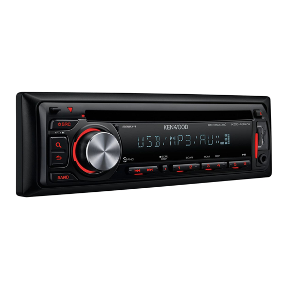
KDC-4047UA/UG/UGY/UM
KDC-414UA/414UM
KDC-MP245U
KDC-U3046/U346/U4046
SERVICE MANUAL
KDC-4047UA/UG : Panel assy (A64-5002-12)
KDC-4047UM : Panel assy (A64-5131-12)
KDC-414UM : Panel assy (A64-5132-12)
KDC-U3046 : Panel assy (A64-5008-12)
KDC-U4046 : Panel assy (A64-5016-12)
Escutcheon
* Carrying case
(B07-3270-01)
(W01-1710-05)
Mounting hardware assy
(J22-0789-03)
* Screw (4x16)
(N84-4016-48)
* Depends on the model. Refer to the parts list.
KDC-4047U
KDC-4047UM
KDC-414UM
KDC-U3046
KDC-U4046
* DC cord
* DC cord
(E30-xxxx-xx)
(E30-xxxx-xx)
* Screw set
Lever
(N99-1757-15)
(D10-7106-04) x2
© 2009-11 PRINTED IN JA PAN
B53-0767-10 ( N ) 341
KDC-4047UGY : Panel assy (A64-5004-12)
KDC-414UA : Panel assy (A64-5003-12)
KDC-MP245U : Panel assy (A64-5001-12)
KDC-U346 : Panel assy (A64-5009-12)
TDF SPARE-PANEL
MAIN UNIT NAME
TDF PARTS No.
KDC-4047UA
Y33-3242-73
KDC-4047UG
Y33-3242-74
KDC-4047UGY
Y33-3242-76
KDC-4047UM
Y33-3250-23
KDC-414UA
Y33-3242-75
KDC-414UM
Y33-3250-24
KDC-MP245U
Y33-3240-11
KDC-U3046
Y33-3250-21
KDC-U346
Y33-3250-22
KDC-U4046
Y33-3253-02
* Remote controller assy (RC-405)
(A70-2104-05)
* Plastic cabinet assy
(A02-2755-23)
This product uses Lead Free solder.
This product complies with the
KDC-4047UGY
KDC-414U
KDC-MP245U
KDC-U346
TDF NAME
TDF-4047UA
TDF-4047UG
TDF-4047UGY
TDF-4047UM
TDF-414UA
TDF-414UM
TDF-MP02DU
TDF-U3046
TDF-U346
TDF-U4046
RoHS
directive for the European market.
Advertisement
Table of Contents

Related Manuals for Kenwood KDC-4047UGY


Summarization of Contents
COMPONENTS DESCRIPTION
SWITCH UNIT (X16-675x-xx) Components
Description of components for the switch unit.
ELECTRIC UNIT (X34-660x-xx) Components
Description of components for the electric unit.
CD PLAYER UNIT (X32-6250-00) Components
Description of components for the CD player unit.
MICROCOMPUTER'S TERMINAL DESCRIPTION
SYSTEM µ-COM : IC1 Terminal Details
Terminal details for the system microcomputer IC1.
Bolero µ-COM : IC900 Terminal Details
Terminal details for the Bolero microcomputer IC900.
TEST MODE
Test Mode Entry and Exit Procedures
Procedures for entering and clearing the test mode.
Test Mode Operations and Specifications
Covers default conditions, standby specs, and general operations.
Tuner Adjustment and Evaluation Modes
Details tuner setting, adjustment modes, and S-meter evaluation.
Media and System Testing Procedures
Covers CD-DA, compressed media, RDS, and channel switching.
Data Management and Updates
Procedures for backup current, DC offset clear, and forced updates.
PC BOARD LAYOUT
Component Side View
Diagram showing component placement on the PC board.
Foil Side View
Diagram showing the foil traces on the PC board.
SCHEMATIC DIAGRAM
ELECTRIC UNIT Schematics
Schematic diagram of the electric unit.
SWITCH UNIT PC BOARD LAYOUT
Component and Foil Side Views
Diagrams showing PC board layout and connections.
CD PLAYER UNIT PC BOARD LAYOUT
Component and Foil Side Views
Diagrams showing PC board layout and connections.
PARTS LIST
SWITCH UNIT Parts List
List of parts for the switch unit.
CD PLAYER UNIT Parts List
List of parts for the CD player unit.
ELECTRIC UNIT Parts List
List of parts for the electric unit.
MECHANISM ASSY Parts List
List of parts for the mechanism assembly.
COMPONENT DETAILS
CAPACITORS
Details and specifications for capacitors.
RESISTORS
Details and specifications for resistors.
Need help?
Do you have a question about the KDC-4047UGY and is the answer not in the manual?
Questions and answers