Advertisement
Table of Contents
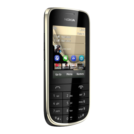
Nokia Asha
202 / 2020
RM-834
1
SERVICE MANUAL
Level 1&2
Nokia I nternal Use Only | Copyright © 2012 Nokia | A ll rights reserved
Nokia Asha 202 /2020 (RM-834)
Nokia Asha 203 /2030 (RM-832/RM-833)
L1L2 Service Manual
Nokia Asha
203 / 2030
RM-832/RM-833
Transceiver characteristics
Band
EGSM 850/1900 MHz (RM-833)
EGSM 900/1800 MHz (RM-832/RM-834)
Display
2.4" QVGA TFT display, 320x240 pixels
Camera
2 Mpix camera with 4x digital zoom
Operating System
S40
Connections
3.5mm AV Jack
2.0mm DC Jack
Micro USB
Micro SD card slot
Transceiver with BL-5C battery pack
Talk time
GSM: Up to 5.8
GSM: Up to 610
hours
hours
Note:
Talk times are dependent on network
parameters and phone settings
Standby
Version 1.0
Advertisement
Table of Contents

Related Manuals for Nokia RM-834


Summarization of Contents
Transceiver Characteristics
Band
Lists frequency bands for different models.
Display
Details screen resolution and size.
Camera
Specifies camera resolution and zoom.
Operating System
Identifies the phone's OS.
Connections
Lists available ports and connectors.
Battery and Talk Time
Details battery type and talk/standby times.
Warnings and Cautions
General Warnings
Lists critical safety warnings for operation.
Service Cautions
Outlines precautions for servicing personnel.
Service Devices
CA-101 Service Cable
USB cable for data transfer.
AC-11 Travel Charger
Charger for the device.
Battery BL-5C
Standard battery pack.
SS-276 Camera Removal Tool
Tool for camera component removal.
Nokia Standard Toolkit (v2)
Comprehensive toolkit for service.
Disassembly Instructions
Initial Steps and Tools
General disassembly note and required tools.
Cover Removal
Steps for protecting and removing the A and B covers.
Screw Removal
Instructions for unscrewing specific screws.
A-COVER Snap Release
Releasing snaps holding the A-COVER.
A-COVER Removal
Lifting and releasing the A-COVER.
Component Protection
Protecting Display and Touch Window.
Keymat Removal
Releasing and removing the keymat.
Earpiece and Gasket Removal
Removing Earpiece and Earpiece Gasket.
Screw and SIM Cover Removal
Unscrewing board screws and removing SIM2 Cover.
Engine Board Separation
Separating the engine board from the D-COVER.
UI Shielding Clips
Releasing clips on the UI Shielding.
UI Shielding Removal
Releasing clips and removing UI Shielding.
Display Disconnection and Removal
Disconnecting and removing the display.
Domesheet Removal
Releasing and peeling off the domesheet.
Camera Removal
Removing the camera using a specific tool.
Lock Key and Volume Key Removal
Pulling out the Lock and Volume keys.
SIM2 Cover Sliding
Sliding and removing the SIM2 Cover.
IHF Speaker and Gasket Removal
Releasing and removing IHF Speaker and Gasket.
AV and DC Jack Removal
Levering out AV and DC jacks.
Antenna Release and Removal
Releasing and removing the antenna.
Disassembly Completion
Final step indicating procedure completion.
Assembly Hints
TORX+ Size 6 Screw Tightening
Tightening four TORX+ size 6 screws to 16 Ncm.
TORX+ Size 4 RF1.4x4.0 Screw Tightening
Tightening two TORX+ size 4 RF1.4x4.0 screws to 12 Ncm.
TORX+ Size 4 M1.4x3.4 Screw Tightening
Tightening two TORX+ size 4 M1.4x3.4 screws to 12 Ncm.
Solder Components
Keypad LED Components
Identifies Keypad LED components (V2403, V2404).
Fuse Components
Identifies Charger and USB fuse components (F2051, F2050).
Switch Components
Identifies Volume/Zoom switch components (S2421, S2420).
Lock Key Component
Identifies the Lock key component (S2422).
Antenna Spring Components
Identifies antenna GND and main antenna springs (X7452, X7451).
Need help?
Do you have a question about the RM-834 and is the answer not in the manual?
Questions and answers