Table of Contents
Advertisement
Quick Links
Downloaded From CamcorderManual.com Panasonic Manuals
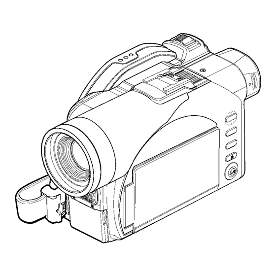
DVD Video Camera/Recorder
VDR-M70EG
VDR-M70EB
VDR-M70GC
VDR-M50EG
VDR-M50EB
VDR-M50GC
(M70) or "TYPE M70" and (M50) or "TYPE M50" in this
manual stands for the model shown below.
(M70) or "TYPE M70": VDR-M70EG, EB, GC
(M50) or "TYPE M50": VDR-M50EG, EB, GC
© 2004 Matsushita Electric Industrial Co., Ltd. All
rights
reserved.
distribution is a violation of law.
ORDER NO. VM0405024C8
Unauthorized
copying
and
Advertisement
Table of Contents
Troubleshooting

Related Manuals for Panasonic VDR-M50GC


Summarization of Contents
1 SAFTY PRECAUTION FOR REPAIR
1.2. SAFETY PRECAUTIONS
General safety guidelines for service personnel.
2 GENERAL DESCRIPTION
2.2. SPECIFICATIONS
Technical specifications of the camera/recorder models.
3 DESCRIPTION OF OPERATION
3.1. DESCRIPTION OF STRUCTURE
Description of the physical structure and key components.
4 TROUBLESHOOTING
4.1. PROCEDURE FOR TROUBLESHOOTING
Step-by-step guide for diagnosing and resolving issues.
4.3. PROBLEM GUIDE
A guide to common symptoms and their possible causes/corrections.
4.5. SELF-DIAGNOSIS FUNCTION AND TROUBLESHOOTING
Information on the device's self-diagnosis system and error codes.
1 SAFTY PRECAUTION FOR REPAIR
1.1.2. ABOUT LEAD FREE SOLDER (PbF)
Information regarding lead-free solder and handling precautions.
1.2.1. GENERAL GUIDELINES
General guidelines for safe servicing practices.
1.2.2. LEAKAGE CURRENT COLD CHECK
Procedure to check for leakage current when the equipment is off.
1.2.3. LEAKAGE CURRENT HOT CHECK
Procedure to check for leakage current when the equipment is powered on.
1 SAFTY PRECAUTION FOR REPAIR
1.3. PREVENTION OF ELECTRO STATIC DISCHARGE (ESD) TO ELECTROSTATICALLY SENSITIVE (ES) DEVICES
Procedures to prevent damage from static discharge to sensitive components.
1 SAFTY PRECAUTION FOR REPAIR
1.4.1. REPLACEMENT PROCEDURE
Step-by-step procedure for safely replacing the lithium battery.
1 SAFTY PRECAUTION FOR REPAIR
1.5.1. INFORMATION FOR YOUR SAFETY
Important safety information regarding copyright and general warnings.
1.5.2. CAUTION FOR AC MAINS LEAD
Detailed safety precautions for the AC power cord and plug.
2 GENERAL DESCRIPTION
2.1.1. Servicing method
Table detailing the servicing method for various parts of the device.
2 GENERAL DESCRIPTION
2.5.1. NAME OF PARTS
Identification of major external and internal parts of the device.
4 TROUBLESHOOTING
4.2.1. List of items to be reset
Lists items that are reset to factory defaults by system or function reset operations.
4 TROUBLESHOOTING
4.2.2. System reset procedure
Step-by-step procedure for performing a system reset.
4.2.3. Procedure for resetting camera functions
Step-by-step procedure for resetting camera functions.
4 TROUBLESHOOTING
4.5.1. Message displayed by self-diagnosis function
Explains messages displayed by the self-diagnosis function.
4.6. CHECKING VERSIONS OF FIRMWARE AND UPDATING
4.6.1. Checking firmware versions
Procedure to check the current firmware versions installed on the device.
4.6.2. Updating firmware
Instructions on how to update the device's firmware.
4.7. TROUBLE DIAGNOSIS
4.7.1. Trouble diagnosis table
A table to help diagnose problems by checking specific points.
4.8. PROCEDURE FOR REMOVING DISC FROM FAULTY VDR-M70/M50
4.8.1. Item to be checked
Preliminary checks before attempting to remove a disc.
4.8.2. How to remove disc
Step-by-step instructions for manually removing a disc.
4.9. SPECIAL FUNCTIONS
4.9.1. Forced formatting of DVD-RAM disc
Procedure for forced formatting of DVD-RAM discs when normal formatting fails.
4.9.2. EEPROM data backup and write
(4) Write method
Procedure for writing EEPROM data from a backup file to a new EEPROM.
5 DISASSEMBLY AND REASSEMBLY
5.1. ITEM TO BE CHECKED
Preliminary checks before disassembling the unit.
5.2. ORDER OF DISASSEMBLY
Step-by-step instructions for disassembling the device.
5.3. DISASSEMBLY
(1) Adjustment Cover
Steps to remove the adjustment cover from the device.
(2) Hood, Filter Piece and Lens Cover
Steps to remove the hood, filter piece, and lens cover.
5.3. DISASSEMBLY
(3) SAF-H/SAF Circuit Board and L Block
Procedure to remove the SAF-H/SAF circuit board and L block.
5.3. DISASSEMBLY
(4) Front Block and R Block
Steps to remove the front block and R block.
(5) Jack Cover
Procedure to remove the jack cover.
(6) FRT-H/FRT circuit board, Microphone, and Microphone Cover
Steps to remove the FRT-H/FRT board, microphone, and cover.
5.3. DISASSEMBLY
(7) Side Case L, LCD Unit, and SWL2 Circuit Board
Procedure to remove the side case L, LCD unit, and SWL2 circuit board.
5.3. DISASSEMBLY
(8) LCD Case-U, MR Circuit Board, and Fulcrum Block
Steps to remove LCD case U, MR circuit board, and fulcrum block.
5.3. DISASSEMBLY
(9) Disc Cover
Procedure to remove the disc cover, including cautions for reassembly.
5.3. DISASSEMBLY
(10) USB Holder, USB-H/USB Circuit Board, Rear Cover, EVF Unit, and Hand Strap
Steps to remove USB holder, boards, rear cover, EVF unit, and hand strap.
5.3. DISASSEMBLY
(11) SHE-H Circuit Board and Accessory Shoe in VDR-M70
Procedure to remove SHE-H circuit board and accessory shoe in VDR-M70.
(12) SHE Circuit Board in VDR-M50
Procedure to remove the SHE circuit board in VDR-M50.
(13) Accessory Shoe in VDR-M50
Procedure to remove the accessory shoe in VDR-M50.
5.3. DISASSEMBLY
(14) AEL-H/AEL and MAN-H/MAN Circuit Boards
Procedure to remove AEL-H/AEL and MAN-H/MAN circuit boards.
5.3. DISASSEMBLY
(15) Camera Block
Steps to remove the camera block assembly.
(16) Link Bracket
Procedure to remove the link bracket.
5.3. DISASSEMBLY
(17) Drive Block and Side Case-R
Steps to remove the drive block and side case-R.
5.3. DISASSEMBLY
(18) Loader, DRF-H/DRF Circuit Board, Disc Drive Unit, Lock Unit, and Frame
Steps to remove loader, DRF/DRF board, disc drive, lock unit, and frame.
5.3. DISASSEMBLY
(19) Fulcrum Cover-U, Fulcrum Cover-B and Fulcrum Unit
Steps to remove fulcrum covers and unit.
(20) LCD Case-B and LCD Circuit Board
Steps to remove LCD case B and LCD circuit board.
5.3. DISASSEMBLY
(21) GYR-H Circuit Board, Lens Frame, Lens Unit, Cushion, Crystal Filter, CCD Image Sensor, and SEN-H Circuit Board in VDR-M70
Steps to remove GYR-H board, lens frame, lens unit, cushion, filter, CCD, and SEN-H board in VDR-M70.
5.3. DISASSEMBLY
(22) GYR Circuit Board, Lens Frame, and Lens Unit in VDR-M50
Steps to remove GYR board, lens frame, and lens unit in VDR-M50.
6 ADJUSTMENT
6.1. CREATING REFERENCE DATA
Process for creating necessary reference data for adjustments.
6.1. CREATING REFERENCE DATA
6.1.1. List of Jigs and Tools used when Creating Reference Data
Lists necessary jigs and tools for creating reference data.
6.1. CREATING REFERENCE DATA
6.1.2. Power Supply and Materials for Creating Reference Data
Lists power supplies and materials required for creating reference data.
6.1.3. Connections when Creating Reference Data
Describes how to connect equipment for creating reference data.
6.2. SETUPS FOR ADJUSTMENT
6.2.1. Checking Reference Data
Flowchart to determine if reference data creation is necessary before adjustment.
6.2.2. List of Jigs and Tools for Adjustment
Lists jigs and tools required for performing adjustments.
6.2.5. Settings for Adjustment
(2) Setting test equipment
Instructions for setting up test equipment like oscilloscopes and vectorscopes.
6.3. LIST OF ADJUSTMENT ITEMS
6.3.1. Adjustment Program Hierarchy Diagram
Visual representation of the adjustment program's structure and available options.
6.4. ADJUSTMENT PROCEDURE
6.4.1. Initial Data Write
Procedure to write initial data to EEPROM after component replacement.
6.4.10. LCD
(1) LCD PLL
Procedure to adjust the LCD PLL frequency for video synchronization.
(2) LCD Contrast-1
Procedure to adjust the LCD contrast setting (first part).
(3) LCD Brightness
Procedure to adjust the LCD brightness setting.
(4) LCD Contrast-2
Procedure to adjust the LCD contrast setting (second part).
(5) LCD White Balance
Procedure to adjust LCD white balance settings for accurate color.
6.4.11. EVF
(1) EVF BL DET Check
Checks the EVF backlight for identification of unit types.
(2) EVF PLL
Procedure to adjust the EVF PLL frequency for video synchronization.
(3) EVF Contrast
Procedure to adjust the EVF contrast setting.
(4) EVF Brightness
Procedure to adjust the EVF brightness setting.
(5) EVF White Balance
Procedure to adjust EVF white balance for accurate color.
7 SCHEMATIC, CIRCUIT BOARD AND BLOCK DIAGRAMS
S-1 VDR-M70 Wiring Diagram
Wiring diagram for the VDR-M70 model, showing connections between components.
S-2 VDR-M50 Wiring Diagram
Wiring diagram for the VDR-M50 model, showing connections between components.
S-3 GYR-H/GYR S-4 FRT-H/FRT
Schematic diagrams for the GYR-H/GYR and FRT-H/FRT circuit boards.
S-5 DRF-H/DRF Schematic Diagram
Schematic diagram for the DRF-H/DRF circuit board.
S-7 SHE-H S-8 SHE
Schematic diagrams for the SHE-H and SHE circuit boards.
AUD [AEL-H/AEL] SCHEMATIC DIAGRAM
Schematic diagram for the AUD [AEL-H/AEL] section.
S-9 USB-H/USB S-10 SAF-H/SAF S-11 MR
Schematic diagrams for USB-H/USB, SAF-H/SAF, and MR circuit boards.
S-13 SEN-H
Schematic diagram for the SEN-H circuit board.
LENS DRIVE [AEL-H/AEL] SCHEMATIC DIAGRAM
Schematic diagram for the lens drive [AEL-H/AEL] section.
S-14 BTB [AEL-H/AEL]
Schematic diagram for the BTB [AEL-H/AEL] connection.
S-17 EVF [AEL-H/AEL]
Schematic diagram for the EVF [AEL-H/AEL] section.
S-18 SWL2
Schematic diagram for the SWL2 circuit board.
S-19 IC BLOCK
Block diagrams showing the ICs used in the device.
C Circuit Board Diagrams
C-1 GYR-H
Circuit board diagram for the GYR-H component.
C-3 FRT-H
Circuit board diagram for the FRT-H component.
C-4 FRT
Circuit board diagram for the FRT component.
C-5 DRF-H/DRF
Circuit board diagram for the DRF-H/DRF component.
C-6 SHE
Circuit board diagram for the SHE component.
C-7 SHE-H
Circuit board diagram for the SHE-H component.
C-8 SWL2
Circuit board diagram for the SWL2 component.
C-9 USB-H/USB
Circuit board diagram for the USB-H/USB component.
C-10 MR
Circuit board diagram for the MR component.
C-11 LCD
Circuit board diagram for the LCD component.
C-12 SEN-H
Circuit board diagram for the SEN-H component.
C-13 SAF-H/SAF
Circuit board diagram for the SAF-H/SAF component.
C-14 AEL-H/AEL
Circuit board diagram for the AEL-H/AEL component.
C-15 MAN-H/MAN
Circuit board diagram for the MAN-H/MAN component.
C-16 DRV-R
Circuit board diagram for the DRV-R component.
C-17 MOD
Circuit board diagram for the MOD component.
C-18 HDM
Circuit board diagram for the HDM component.
B Block Diagrams
B-1 Video/Audio Signal Process
Block diagram illustrating the video and audio signal processing path.
B-2 Disc Drive
Block diagram of the disc drive mechanism and its components.
B-3 Power-1
Block diagram of the power supply system (Part 1).
B-4 Pr-2
Block diagram of the power supply system (Part 2).
8 EXPLODED VIEWS
8.1. MAIN SECTION
Exploded view of the main mechanical section of the device.
8.2. LCD BLOCK SECTION
Exploded view of the LCD display assembly.
8.3. CAMERA LENS SECTION
Exploded view of the camera lens components.
8.3.1. For VDR-M70
Exploded view of the camera lens components specifically for the VDR-M70.
8.3.2. For VDR-M50
Exploded view of the camera lens components specifically for the VDR-M50.
8.4. EVF BLOCK SECTION
Exploded view of the electronic viewfinder (EVF) assembly.
8.5. PACKING PARTS & ACCESSORIES SECTION
Diagram showing how the product and accessories are packed.
9 REPLACEMENT PARTS LIST
9.1. MECHANICAL REPLACEMENT PARTS LIST
List of mechanical parts available for replacement.
9.1.1. FRAME & CASING SECTION PARTS LIST
List of mechanical replacement parts for the frame and casing.
9.1.2. CAMERA LENS SECTION PARTS LIST
List of replacement parts for the camera lens section.
9.1.3. EVF SECTION PARTS LIST
List of replacement parts for the EVF section.
9.2. ELECTRICAL REPLACEMENT PARTS LIST
List of electrical components available for replacement.
Need help?
Do you have a question about the VDR-M50GC and is the answer not in the manual?
Questions and answers