Advertisement
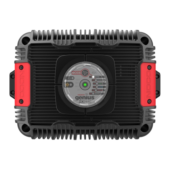
GXSeries
DANGER
Welcome.
GX Series Smart Charger. Read and understand the
User Guide before operating the charger. For questions
regarding our chargers, view our comprehensive support
information at www.no.co/support. To contact NOCO for
personalized support (not available in all areas), visit
www.no.co/connect.
What's In The Box.
• GX Series Smart Charger
• AC Cable
• User Guide
• Information Guide and Warranty
User Guide
PRIOR TO USE, READ AND UNDERSTAND
PRODUCT SAFETY INFORMATION.
Failure to follow the instructions may result
in ELECTRICAL SHOCK, EXPLOSION,
or FIRE, which may result in SERIOUS
INJURY, DEATH, DAMAGE TO DEVICE or
PROPERTY. Do not discard this information.
Thank you for buying a NOCO Genius
®
Advertisement
Table of Contents

Summarization of Contents
Understanding Charging Modes
Standby Mode
Charger is not charging, Energy Save active, indicated by an orange LED.
NORM Mode
For Wet Cell, Gel Cell, Calcium, EFB batteries. Indicated by a white LED.
COLD/AGM Mode
For cold temperatures or AGM batteries. Indicated by a blue LED.
Advanced Charging Modes
AGM+ Mode
For advanced AGM batteries requiring higher voltage. Indicated by a blue LED.
LI-ION Mode
For lithium-ion batteries, including LiFePO4. Indicated by a blue LED.
REPAIR Mode
Battery recovery for old, damaged, or sulfated batteries. Indicated by a red LED.
SUPPLY Mode
Converts charger to a DC power supply. Indicated by a red LED.
Cable and Port Connections
AC Input Connection Port
Connects the charger to an AC power source (line, return, ground).
DC Output Connection Port
Connects the charger to the battery terminals (positive and negative).
Inhibit and Remote LEDs Ports
Optional ports for controlling external devices and monitoring LEDs.
Connecting and Beginning Charging
Connecting to the Battery
Step-by-step instructions for safely connecting the charger to battery terminals.
Begin Charging
Steps to verify connections, select mode, and start the charging process.
User Interface and Diagnostics
User Interface Overview
Diagram of controls and LEDs including Mode Button, Charge LEDs, and Error LED.
Understanding Charge LEDs
Explanation of 25%, 50%, 75%, 100% LEDs indicating battery state-of-charge.
Advanced Diagnostics
Interpreting error codes via LED flash patterns for troubleshooting.
Charging Process and Specifications
Charging Steps
Details the 9-step smart charging process from Analyze to Maintenance.
Technical Specifications
Lists key technical details including voltage, current, dimensions, and weight.


Need help?
Do you have a question about the GX4820 and is the answer not in the manual?
Questions and answers