Table of Contents
Advertisement
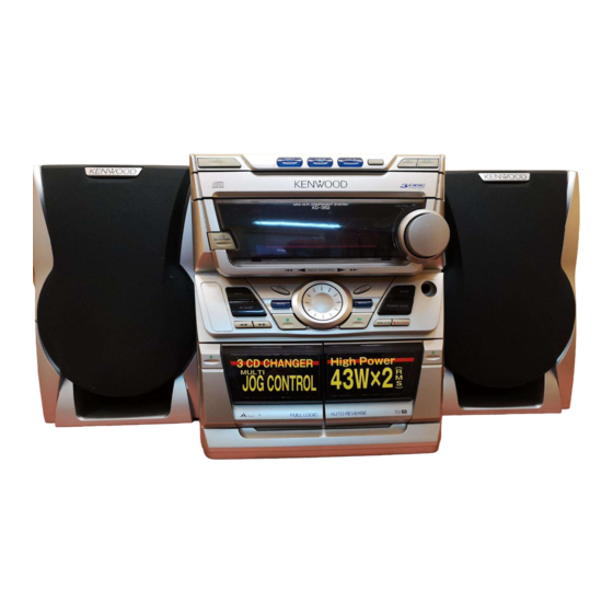
MINI HiFi COMPONENT SYSTEM
RXD-302/302E/352/352E/372S
QQ
3 7 63 1515 0
LS-N302/N352
SERVICE MANUAL
(XD-302/302E/352/352E/372S)**
OPEN/CLOSE button
(K29-7646-08)
Front window
(A29-1071-08)
POWER button
(K29-7650-08)
Knob (JOG)
TE
L 13942296513
(K29-7658-08)
EX. BASS button assy
(K29-7642-08)
Knob (STOP)
(K29-7654-08)
Cass window L
(B10-3527-08)
Cass door L
(A53-2158-08)
www
**Refer to page 2 if you want to know system configuration.
In compliance with Federal Regulations, following are reproduc-
tions of labels on, or inside the product relating to laser product
safety.
.
Refer to service manual RXD-251/301/301E/301W/351/
351E/351W/371S (B51-5454-00), if you require CD MECH-
ANISM OPERATION DESCRIPTION in detail.
DISC button bass assy
(K29-7641-08)
ON/STANDBY
INPUT
MENU
EX.BASS
A
PLAY
x
ao
u163
y
i
2 9
8
PLAY PAUSE button
(K29-7648-08)
1
2
3
DISC
DISC
DISC
DISC SKIP
MULTI CONTROL
Q Q
3
6 7
1 3
1 5
SELECT
TUNING MODE
TAPE A/B
KENWOOD-Crop. certifies this equipment conforms to DHHS
co
Regulations No. 21 DFR 1040. 10, Chapter 1, Subchapter J.
DANGER : Laser radiation when open and interlock defeated.
.
AVOID DIRECT EXPOSURE TO BEAM
9 4
2 8
© 1999-5/B51-5530-00 (K/K) 2299
CD door
(A60-1723-08)
VOLUME
Knob (VOLUME)
(K29-7652-08)
0 5
8
2 9
9 4
PHONES
Headphone jack
BAND
(E11-0386-08)
Tuning button assy
(K29-7643-08)
REC/ARM
PLAY button
(K29-7656-08)
Cass window R
(B10-3528-08)
Cass door R
(A53-2159-08)
REC/
B
PLAY
m
Illust. is RXD-352M.
9 9
2 8
9 9
Advertisement
Table of Contents

Related Manuals for Kenwood RXD-352


Summarization of Contents
Accessories
FM Indoor Antenna (Europe/UK)
Accessory for FM reception in Europe and UK.
FM Indoor Antenna (Other Countries)
Accessory for FM reception in other countries.
Remote Control Unit
Remote control unit for system operation.
AM Loop Antenna
Accessory for AM reception.
AC Plug Adaptor
Adaptor for power cord to wall outlet.
Cautions
Operation to Reset Microcomputer
Procedure to reset the microcomputer and return to normal condition.
External View
Top Cabinet
The top section of the component unit.
Rear Panel Connections
Phono jack, antenna terminal, lock terminal board, slide switch, AC power cord.
Block Diagram
Tuner Unit Block Diagram
Shows the internal connections of the tuner section.
Main PCB and CD Mecha. Unit Blocks
Illustrates main processing and CD mechanism connections.
Circuit Description
Main Microprocessor and Peripherals
Details the main microprocessor (IC601) and its connected components.
Voltage Key/Band Matrix
Table mapping input voltages to key functions and band settings.
Pin Description
Microprocessor and Control IC Pinouts
Detailed pin descriptions for key ICs and control signals.
Component and Switch Pin Assignments
Pin assignments for various components, switches, and interfaces.
Adjustment Procedures
FM Section Adjustments (Non-M2)
Calibration steps for FM reception (except M2 type).
MW Section Adjustments (Non-M2)
Calibration steps for MW reception (except M2 type).
Adjustment Procedures
SW and LW Section Adjustments
Calibration steps for SW and LW tuner sections.
Instruments Connection for Adjustment
Diagram showing required instruments and their connections for calibration.
Cassette Deck Adjustment
Cassette Mechanism Adjustments
Procedures for REC/PB head and azimuth adjustments.
PC Board Adjustments (Cassette)
Adjustments for tape speed and playback level on the PC board.
CD Section Adjustment
Laser Power Calibration
Procedure to calibrate the CD player laser power output.
PC Board Layouts
Tuner Unit PC Board
Component placement diagram for the Tuner Unit PCB.
CD Unit PC Board
Component placement diagram for the CD Unit PCB.
PC Board Layouts
Tuner Unit PC Board (Details)
Detailed component layout for the Tuner Unit PCB.
PC Board Layouts
Main Unit PC Board
Component placement diagram for the Main Unit PCB.
Front Unit PC Board
Component placement diagram for the Front Unit PCB.
Schematic Diagrams
Tuner Unit Schematic
Circuit diagram for the Tuner Unit.
System Schematic Overview
Overall circuit diagram for the RXD series.
Schematic Diagrams
Main Unit and CD Unit Schematics
Circuit diagrams for the Main Unit and CD Player sections.
Schematic Diagrams
Front Unit and Power Supply Schematics
Circuit diagrams for the Front Unit and power supply.
Schematic Diagrams
Cassette Deck and Amplifier Schematics
Circuit diagrams for the Cassette Deck and Amplifier sections.
Schematic Diagrams
Power Amplifier and System Configuration Schematics
Diagrams for power amplifier, system configurations, and transformers.
Schematic Diagrams
Microcontroller and Control Logic Schematics
Circuit diagrams for the microcontroller (UCON) and related logic.
Schematic Diagrams
Front Panel Control Schematics
Circuit diagrams for the front panel controls and displays.
Exploded Views
CD Mechanism Exploded View
Exploded diagram showing CD mechanism parts and assembly.
Exploded Views
CD Mechanism Parts Details
Detailed exploded view of CD mechanism components and part numbers.
Exploded Views
Unit Components Exploded View
Exploded diagram of the main unit's external and internal components.
Parts List
Model and Destination Abbreviations
Abbreviations for models and their production destinations.
Mechanical Parts List
List of mechanical components with part numbers and descriptions.
Parts List
Tuner Unit Components
List of electronic components for the Tuner Unit.
Parts List
Tuner Unit (M2 Type) Components
List of electronic components for the M2 type Tuner Unit.
Parts List
Main Unit Components
List of electronic components for the Main Unit.
Parts List
Miscellaneous Components and Transistors
List of various components, transistors, diodes, and ICs.
Parts List
Front Unit and CD Mechanism Components
Lists components for the Front Unit and CD Mechanism.
Parts List
CD Mechanism (D40-1652) and Speaker Parts
Lists CD mechanism and speaker components.
Parts List
Reading the Parts List
Instructions on how to interpret the parts list.
Specifications
Main Unit Specifications
Technical specifications for the amplifier, tuner, and other main unit functions.
Cassette Deck and CD Player Specifications
Technical specifications for the cassette deck and CD player sections.
Speaker Specifications
Technical specifications for the LS-N302/LS-N352 speaker system.
Need help?
Do you have a question about the RXD-352 and is the answer not in the manual?
Questions and answers