Table of Contents
Advertisement
SERVICE MANUAL
Ver. 1.2 2010.11
FOR UNITED STATES CUSTOMERS. NOT
APPLICABLE IN CANADA, INCLUDING
IN THE PROVINCE OF QUEBEC.
POUR LES CONSOMMATEURS AUX
ÉTATS-UNIS. NON APPLICABLE AU
CANADA, Y COMPRIS LA PROVINCE DE
QUÉBEC.
AUDIO POWER SPECIFICATIONS
(US model only)
CEA2006 Standard
Power Output: 17 Watts RMS
4 Ohms < 1% THD+N
SN Ratio: 82 dBA
(reference: 1 Watt into 4 Ohms)
Monitor section
Display type: Wide LCD color monitor
Dimensions: 6.1 in
System: TFT active matrix
Number of pixels: 1,152,000 pixels
Color system:
PAL/NTSC/SECAM/PAL-M automatic select
Tuner section
FM
Tuning range:
US and Canadian models: 87.5 – 107.9 MHz
AEP and UK models: 87.5 – 108.0 MHz
Russian model:
FM1/FM2: 87.5 – 108.0 MHz
(at 50 kHz step)
FM3: 65 – 74 MHz (at 30 kHz step)
Asian model:
87.5 – 108.0 MHz (at 50 kHz step)
Latin American model:
87.5 – 107.9 MHz (at 200 kHz step)
Saudi Arabia model:
87.5 – 108.0 MHz (at 50 kHz step)
Antenna (aerial) terminal:
External antenna (aerial) connector
Intermediate frequency: 150 kHz
Usable sensitivity: 10 dBf
Selectivity: 75 dB at 400 kHz
Signal-to-noise ratio: 70 dB (mono)
Separation: 40 dB at 1 kHz
Frequency response: 20 – 15,000 Hz
9-889-748-03
Sony Corporation
2010K05-1
©
2010.11
Published by Sony Techno Create Corporation
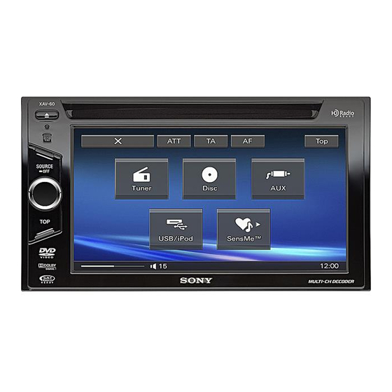
Photo: XAV-60
SPECIFICATIONS
AM (US and Canadian models)
Tuning range: 530 – 1,710 kHz
Antenna (aerial) terminal:
External antenna (aerial) connector
Intermediate frequency: 25 kHz
Sensitivity: 26 µV
AM (E model)
Tuning range:
Asian model:
531 – 1,602 kHz (at 9 kHz step)
Latin American model:
530 – 1,710 kHz (at 10 kHz step)
Saudi Arabia model:
4 at
531 – 1,602 kHz (at 9 kHz step)
Antenna (aerial) terminal:
External antenna (aerial) connector
Intermediate frequency: 25 kHz
Sensitivity: 26 µV
MW/LW (AEP, UK and Russian model)
Tuning range:
MW: 531 – 1,602 kHz
LW: 153 – 279 kHz
Antenna (aerial) terminal:
External antenna (aerial) connector
Intermediate frequency: 25 kHz
Sensitivity: MW: 26 µV, LW: 45 µV
DVD/CD Player section
Signal-to-noise ratio: 120 dB
Frequency response: 10 – 20,000 Hz
Wow and flutter: Below measurable limit
Harmonic distortion: 0.01 %
Region code: Labeled on the bottom of the unit
USB Player section
Interface: USB (Full-speed)
Maximum current: 500 mA
Power amplifier section
Outputs: Speaker outputs
Speaker impedance: 4 – 8 ohms
Maximum power output: 52 W × 4 (at 4 ohms)
General
Outputs:
Video output terminal (rear)
Audio output terminals (front/rear)
Subwoofer output terminal
Power antenna (aerial) relay control terminal
Power amplifier control terminal
XAV-60/E60
Model Name Using Similar Mechanism
Mechanism Type
Optical Pick-up Name
Inputs:
Telephone ATT control terminal
Illumination control terminal
BUS control input terminal
(US and Canadian models only)
Remote controller input terminal
Antenna (aerial) input terminal
Parking break control terminal
Reverse input terminal
Camera input terminal
AUX audio input terminals
AUX video input terminals
USB signal input connector
External input terminal
(Asian and Saudi Arabia models only)
Power requirements: 12 V DC car battery
(negative ground (earth))
Dimensions: Approx. 178 × 100 × 173 mm
1
(7
/
× 4 × 6
8
Mounting dimensions: Approx. 182 × 111 × 164 mm
1
(7
/
× 4
4
Mass: Approx. 2.2 kg (4 lb 14 oz)
Supplied accessories:
Card remote commander: RM-X170
Parts for installation and connections (1 set)
Extension cord for AUX audio/video input
terminals
CD-ROM (Application disc)
Your dealer may not handle some of the above listed
accessories. Please ask the dealer for detailed
information.
US and foreign patents licensed from Dolby
Laboratories.
MPEG Layer-3 audio coding technology and
patents licensed from Fraunhofer IIS and Thomson.
This product is protected by certain intellectual
property rights of Microsoft Corporation. Use or
distribution of such technology outside of this
product is prohibited without a license from
Microsoft or an authorized Microsoft subsidiary.
Design and specifications are subject to change
without notice.
US Model
Canadian Model
AEP Model
UK Model
E Model
XAV-60
Russian Model
XAV-E60
NEW
MG-613C-187
KHS-360A
7
/
in) (w/h/d)
8
3
1
/
× 6
/
in) (w/h/d)
8
2
AV CENTER
Advertisement
Table of Contents

Related Manuals for Sony XAV-E60


Summarization of Contents
XAV-60/E60 Service Manual
Specifications
Detailed technical specifications for the XAV-60/E60 unit.
Servicing Notes and Precautions
Handling Optical Pick-up Block
Precautions for handling the optical pick-up block and base unit.
Laser Diode Emission Check
Guidelines for safely checking the laser diode emission from the optical pickup.
Unleaded Solder Information
Characteristics and precautions for using unleaded solder.
General Information, Cautions, and Installation
Unit Cautions and Warnings
Important safety precautions, warnings, and notes for installation and operation.
Connection Diagrams and Examples
Visual guides for connecting the unit to power, speakers, and other components.
Mounting Procedures
Steps and considerations for physically installing the unit in a vehicle.
Ignition Switch Considerations
Handling scenarios where the car ignition lacks an ACC position.
Disassembly Procedures
Disassembly Flow Chart
A flowchart outlining the sequence for disassembling the unit.
Front Panel Block Disassembly
Instructions for removing the front panel assembly.
DVD Mechanism Deck Disassembly
Steps for detaching the DVD mechanism deck from the main chassis.
Chassis 1F and 2F Block Disassembly
Procedures for removing the 1F and 2F chassis blocks.
Audio Board Removal
Steps for removing the audio circuit board.
Visual Board Removal
Instructions for removing the visual circuit board.
Servo Board Removal
Steps for detaching the servo board from the chassis.
Sensor Board and Sub-assy Removal
Procedures for removing the sensor board and related sub-assemblies.
Chassis (OP, ZA) Complete Assembly
Steps for removing the complete optical pick-up assembly.
Electrical Adjustments
Tools and Devices for Adjustment
Required tools and measuring devices for performing electrical adjustments.
Serial Port Configuration
Settings for configuring the serial port for communication with the unit.
Set Connection for Adjustment
Steps for connecting the unit to the adjustment tools.
V-COM Adjustment Procedure
Step-by-step guide for performing the V-COM voltage adjustment.
Flicker Adjustment Procedure
Instructions for adjusting the display to minimize flickering.
Servo Section Diagnostics
IOP Check Procedure
Steps for checking the optical pick-up's IOP value for DVD and CD.
Diagrams and Schematics
Block Diagrams
High-level functional block diagrams of the unit's sections.
Printed Wiring Boards and Schematics
Detailed layout and schematic diagrams of the unit's circuit boards.
Waveform Examples
Visual representations of key signal waveforms for troubleshooting.
IC Block Diagrams
Detailed block diagrams for major integrated circuits used in the unit.
IC Pin Function Descriptions
Pinout descriptions and functions for all major ICs.
Exploded Views
Overall Assembly Exploded View
An exploded view showing the overall assembly of the unit.
Front Panel Section Exploded View
An exploded view detailing the parts of the front panel assembly.
Chassis 2F Section Exploded View
An exploded view of the chassis 2F section components.
Chassis 1F Section Exploded View
An exploded view of the chassis 1F section components.
DVD Mechanism Deck Exploded View
An exploded view showing the parts of the DVD mechanism deck.
Electrical Parts List
Audio Board Components
List of electronic components for the audio board.
Key Board Components
List of components for the key board.
LCD Board Components
List of components for the LCD board.
Servo Board Components
List of electronic components for the servo board.
Visual Board Components
List of electronic components for the visual board.
Revision History
Version Revision Details
Information on changes and updates made to the service manual.
Need help?
Do you have a question about the XAV-E60 and is the answer not in the manual?
Questions and answers