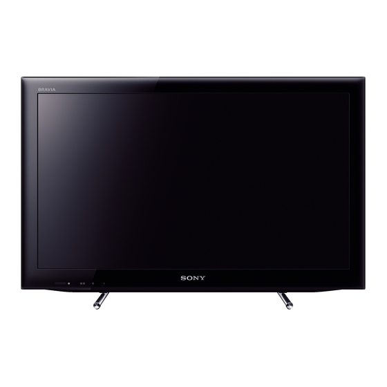
Table of Contents
Advertisement
HISTORY INFORMATION FOR THE FOLLOWING MANUAL:
SERVICE MANUAL
ORIGINAL MANUAL ISSUE DATE: 3/2012
Version
Date
1.0
3/2012
2.0
9/2012
KDL-22EX553/KDL-26EX553/KDL-32EX653(AEP/UK/IT)
Subject
Original manual issue.
Correction of part number for SCREW (+PSW)(M3x6). (P.19, P.35, P.36, P.52)
Following S/N Range is for (BCN)
1,000,001-1,950,000
AZ3F
Segment: P-2A
LCD Digital Color TV
9-888-481-02
Advertisement
Table of Contents
Troubleshooting

Summarization of Contents
History Information
Version History
Records of manual revisions, including issue dates and subject of changes.
Model List
Model Variations
Lists different TV models, their colors, compatible commanders, and destinations.
Warnings and Cautions - English
General Precautions
Important safety instructions and warnings for service personnel and handling.
LCD Panel Handling
Specific guidelines and precautions for safely handling the LCD panel during service.
Safety Check-out
Post-Repair Safety Checks
Essential safety checks to perform before releasing the set to the customer.
Leakage Test and Grounding
Procedures for testing AC leakage and ensuring proper earth grounding.
Self Diagnosis Function
Diagnostic Indicators
Explanation of STANDBY LED flash counts indicating potential problems.
Self-Diagnostic Screen Display
How to access and interpret self-diagnostic screen data for troubleshooting.
SEC 1. DISASSEMBLY
1-1. KDL-22EX550/553/555 Disassembly
Detailed disassembly procedures for KDL-22EX550/553/555 models.
1-2. KDL-26EX550/553/555 Disassembly
Detailed disassembly procedures for KDL-26EX550/553/555 models.
1-3. KDL-32EX650/653/655 Disassembly
Detailed disassembly procedures for KDL-32EX650/653/655 models.
SEC 2. ADJUSTMENT
How to Enter Service Mode
Step-by-step guide to access the TV's service mode using the remote.
Remote Commander Usage in Service Mode
Mapping of remote control buttons to service mode functions and navigation.
Changing Data in Service Modes
Instructions for modifying data within Digital and Chassis service modes.
Saving Changed Data
Procedure to write and save data changes made in Chassis or VPC service modes.
White Balance Adjustment
Guidance on executing white balance adjustments in the VPC service mode.
VCOM Adjustment
Procedure for performing VCOM adjustment in the VPC service mode.
Set to Shipping Condition
Steps to return the TV to its original shipping condition via service mode.
SEC 3. TROUBLE SHOOTING
3-1. Triage Chart
Diagnostic chart correlating symptoms with potential faulty boards or components.
3-2. Flow Chart
General troubleshooting flowchart to diagnose common TV issues.
3-3. No Power Troubleshooting
Specific steps to diagnose and resolve power-related issues.
3-4. Standby LED Blink Codes
Interpreting STANDBY LED blink patterns for error diagnosis, including Main Power, Main Board, T-con, Backlight, Temp, and Software errors.
3-5. Power (Green) LED Blinking
Troubleshooting steps for when the Power (Green) LED is blinking non-stop.
3-6. No Picture Troubleshooting
Diagnostic guide for addressing situations where no picture is displayed.
3-7. No Sound Troubleshooting
Steps to diagnose and resolve audio issues on the TV.
3-8. TV Commander Buttons Malfunction
Troubleshooting TV button and IR remote commander malfunctions.
3-9. Network Malfunction
Diagnostic steps for wired and wireless network connectivity issues.
3-10. Skype Malfunction
Troubleshooting guide for Skype application and connectivity problems.
3-11. HDD-Rec Malfunction
Steps to diagnose and resolve issues with HDD recording functionality.
SEC 4. DIAGRAMS
4-1-1. KDL-22/26EX550/553/555 Block Diagram
Block diagram for KDL-22/26EX550/553/555 models.
4-1-2. KDL-32EX650/653/655 Block Diagram
Block diagram for KDL-32EX650/653/655 models.
4-2-1. KDL-22EX550/553/555 Connector Diagram
Connector pinouts for KDL-22EX550/553/555 models (Part 1/2).
4-2-2. KDL-26EX550/553/555 Connector Diagram
Connector pinouts for KDL-26EX550/553/555 models (Part 1/2).
4-2-3. KDL-32EX650/653/655 Connector Diagram
Connector pinouts for KDL-32EX650/653/655 models (Part 1/2).
4-3. Circuit Boards Location
Visual guide to the physical location of circuit boards within the TV.
SEC 5. EXPLODED VIEWS
5-1. KDL-22EX550/553/555 Exploded Views
Exploded views of parts for KDL-22EX550/553/555 chassis.
5-1-1. Chassis-1
Exploded view of chassis components for KDL-22EX550/553/555.
5-1-2. Chassis-2
Exploded view of chassis components for KDL-22EX550/553/555.
5-2. KDL-26EX550/553/555 Exploded Views
Exploded views of parts for KDL-26EX550/553/555 chassis.
5-2-1. Chassis-1
Exploded view of chassis components for KDL-26EX550/553/555.
5-2-2. Chassis-2
Exploded view of chassis components for KDL-26EX550/553/555.
5-3. KDL-32EX650/653/655 Exploded Views
Exploded views of parts for KDL-32EX650/653/655 chassis.
5-3-1. Chassis-1
Exploded view of chassis components for KDL-32EX650/653/655.
5-3-2. Chassis-2
Exploded view of chassis components for KDL-32EX650/653/655.
5-4. Other Parts and Accessories
Catalog of miscellaneous parts and accessories.
APPENDIX-1
Procedure to Remove Rear Cover
Step-by-step guide with illustrations for removing the rear cover of the TV.


Need help?
Do you have a question about the KDL-22EX555 and is the answer not in the manual?
Questions and answers