Table of Contents
Advertisement
QQ
3 7 63 1515 0
DSP-AX759/DSP-AX759SE
TE
L 13942296513
■ CONTENTS
To Service Personnel ...................................... 2–3
Front Panels ........................................................ 3–5
Rear Panels .......................................................... 5–8
Remote Control Panels ...................................... 9
SPECIFICATIONS / 参考仕様 ................................ 10–12
Internal View ......................................................... 13
DISASSEMBLY PROCEDURES / 分解手順 ......... 14–17
自己診断機能 (ダイアグ)........................................ 18–42
AMP ADJUSTMENT / アンプ部調整 ........................... 43
www
.
1 0 0 9 9 9
http://www.xiaoyu163.com
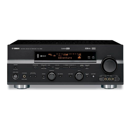
AV RECEIVER/AV AMPLIFIER
RX-V659/HTR-5960
This manual has been provided for the use of authorized YAMAHA Retailers and their service personnel.
It has been assumed that basic service procedures inherent to the industry, and more specifically YAMAHA Products, are already
known and understood by the users, and have therefore not been restated.
WARNING:
Failure to follow appropriate service and safety procedures when servicing this product may result in personal
injury, destruction of expensive components, and failure of the product to perform as specified. For these reasons,
we advise all YAMAHA product owners that any service required should be performed by an authorized
YAMAHA Retailer or the appointed service representative.
IMPORTANT:
The presentation or sale of this manual to any individual or firm does not constitute authorization, certification or
recognition of any applicable technical capabilities, or establish a principle-agent relationship of any form.
The data provided is believed to be accurate and applicable to the unit(s) indicated on the cover. The research, engineering, and
service departments of YAMAHA are continually striving to improve YAMAHA products. Modifications are, therefore, inevitable
and specifications are subject to change without notice or obligation to retrofit. Should any discrepancy appear to exist, please
contact the distributor's Service Division.
WARNING:
Static discharges can destroy expensive components. Discharge any static electricity your body may have
accumulated by grounding yourself to the ground buss in the unit (heavy gauge black wires connect to this buss).
IMPORTANT:
Turn the unit OFF during disassembly and part replacement. Recheck all work before you apply power to the unit.
x
ao
u163
y
i
2006
This manual is copyrighted by YAMAHA and may not be copied or
redistributed either in print or electronically without permission.
http://www.xiaoyu163.com
2 9
8
SERVICE MANUAL
IMPORTANT NOTICE
Q Q
3
6 7
1 3
1 5
Display Data ..................................................... 44–45
Ic Data ................................................................. 46–55
Pin Connection Diagram .............................. 56–57
Block Diagrams .............................................. 59–61
Printed Circuit Boards ................................ 62–78
Schematic DiagramS ...................................... 79–89
REPLACEMENT PARTS LIST ............................ 91–120
REMOTE CONTROL .................................................. 121
ADVANCED SETUP .................................................. 122
co
.
All rights reserved.
9 4
2 8
0 5
8
2 9
9 4
2 8
m
P.O.Box 1, Hamamatsu, Japan
9 9
9 9
'06.02
Advertisement
Table of Contents

Related Manuals for Yamaha DSP-AX759


Summarization of Contents
SELF DIAGNOSIS FUNCTION (DIAG)
Initiate DIAG Mode
Procedure to initiate the self-diagnosis mode on the main unit's controls.
Initiate DIAG in Protection Cancel Mode
Method to bypass protection circuits for diagnosis, enabling entry into DIAG mode.
Exit DIAG Mode
Steps to exit the diagnostic mode, including memory initialization considerations.
DIAG Display Upon Startup
Explains visual feedback on FL display/monitor during DIAG startup, protection status, and menu navigation.
Protection History, Settings, and Menu Navigation
Covers protection history, initial settings, display during operation, and menu/sub-menu navigation.
DIAG Mode Functions and Initial Settings
Lists available functions in DIAG mode and the default settings applied upon starting the diagnostic process.
DIAG Menu Details
1. BYPASS Menu
Allows selection between analog bypass and DSP bypass output modes for audio signal routing.
2. RAM THROUGH Menu
Enables choosing between margin output and full-bit output for RAM data, affecting signal processing.
3. PRO LOGIC Menu
Explains the setup for Dolby PRO LOGIC processing applied to stereo audio inputs.
4. SPEAKERS SET Menu
Outlines analog switch settings for various speaker configurations, including LFE and bass management.
5. XCH INPUT Menu
Manages multi-channel inputs, allowing selection of speaker impedance for optimal signal output.
6. MIC CHECK Menu
Tests microphone input by outputting signals via A/D-D/A; dB display function is not available.
7. DISPLAY CHECK Menu
Verifies the proper operation of the FL display section and video control output signals.
8. MANUAL TEST Menu
Outputs THX-based test noise from the DSP to selected channels for audio system diagnostics.
9. FACTORY PRESET Menu
Manages backup RAM initialization, protecting user settings or resetting to factory defaults.
10. AD DATA CHECK Menu
Displays A/D conversion values for panel keys and protection functions, crucial for hardware diagnostics.
PANEL KEY (K0/K1) Menu
Details the function of panel keys and checks for A/D deviation, essential for input recognition.
11. VIDEO Menu
Explains video signal conversion and output, including I2C communication checks for video processing ICs.
DIGITAL THR Y/C Menu
Details the signal path for digital Y/C video signals through various processing stages.
ANALOG BYPASS Menu
Describes the analog bypass path for video signals, bypassing digital processing for direct output.
TEST PATTERN Menu
Explains the generation and display of test patterns for video output verification.
LOOP BACK CVBS Menu
Details the CVBS loopback test path for verifying video signal integrity.
LOOP BACK Y/C Menu
Details the Y/C loopback test path for verifying video signal integrity.
12. XM STATUS Menu (U, C models)
Checks XM Radio antenna output and test tones, verifying tuner signal reception and processing.
13. iPod Menu
Tests the iPod dock connector for UART loopback and accessory power detection functions.
16. IF STATUS Menu (Input function status)
Displays input/output status data in hexadecimal format, covering various signal processing parameters.
17. DSP BUS CHECK Menu
Diagnoses bus connections for TI DSP and external ROM/RAM, checking for proper communication.
18. SWFR CUT OFF Menu
Details the SWFR cut-off function, likely related to subwoofer output control.
19. PROTECTION SETTING Menu
Allows adjustment or viewing of protection settings related to power supply or thermal limits.
20. PROTECTION HISTORY Menu
Displays a history of past protection events, indicating how many times protection was triggered.
21. SOFT SW Menu
Enables software switching of PCB functions, affecting product operation and protection modes.
Feature Configuration Options Menu
Allows enabling/disabling of features like Zone2, AAC, Tuner, OSD, and YPAO via software settings.
22. SOFTWARE VERSION Menu
Displays microprocessor and DSP software versions, checksums, and port conditions for system identification.
23. TI (DSP) BOOT Menu
Refers to the rewriting mode for TI (DSP) software, crucial for firmware updates or recovery.
AMP ADJUSTMENT / アンプ部調整
CONFIRMATION OF IDLING CURRENT
Details the steps to measure and adjust the idling current of the power amplifier for optimal performance.
GRID ASSIGNMENT
ANODE CONNECTION Details
Details the specific connections and signal assignments for anode terminals across different grounds.
IC DATA: IC504 (LC89057W-VF4-E)
IC504 Pin Details
Lists signal names, I/O types, pull-up/down settings, and GPIO functions for IC504.
IC506: D70YE101RFP250 (DSP P.C.B) Pinout
IC506 Pin Functions: EMIF Bus
Continues the pinout and function details for IC506, covering EMIF data bus and address signals.
IC506 Pin Functions: SDRAM and SPIO/I2C
Further details IC506 pin functions, including SDRAM control and SPIO/I2C interface signals.
IC506 Pin Functions: Serial Data and McASP
Completes the IC506 pinout, detailing serial data pins and McASP interface signals.
IC762 Microprocessor: M30625MHP-A98GP
Microprocessor Pin Assignments
Lists all ports and terminal names for the M30625MHP microprocessor, with PowerOn, I/O, and function details.
Microprocessor Port Functions
Details the specific functions of various microprocessor ports, including relay control, input/output selectors, and protection detection.
Microprocessor Port Functions (Cont.)
Continues the detailed explanation of microprocessor port functions, covering AD key inputs, temperature, and destination detection.
BLOCK DIAGRAMS
OPERATION Block Diagram
Refers to specific pages for detailed operation of audio signal processing blocks.
DSP Block Diagram
Highlights the Digital Signal Processor section and its related signal paths.
VIDEO Block Diagram
Points to schematic diagrams detailing the video signal processing circuitry.
SUBTRANS Block Diagram
Refers to schematic diagrams for the sub-transformer and related audio signal paths.
Need help?
Do you have a question about the DSP-AX759 and is the answer not in the manual?
Questions and answers