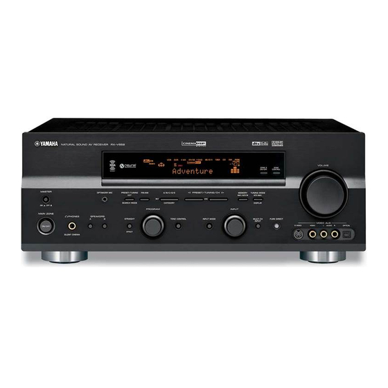
Yamaha RX-V659 Service Manual
Hide thumbs Also See for RX-V659:

Advertisement

QQ
3 7 63 1515 0
DSP-AX759/DSP-AX759SE
TE
L 13942296513
■ CONTENTS
To Service Personnel ...................................... 2–3
Front Panels ........................................................ 3–5
Rear Panels .......................................................... 5–8
Remote Control Panels ...................................... 9
SPECIFICATIONS / 参考仕様 ................................ 10–12
Internal View ......................................................... 13
DISASSEMBLY PROCEDURES / 分解手順 ......... 14–17
自己診断機能 (ダイアグ)........................................ 18–42
AMP ADJUSTMENT / アンプ部調整 ........................... 43
www
.
1 0 0 9 9 9
http://www.xiaoyu163.com
AV RECEIVER/AV AMPLIFIER
RX-V659/HTR-5960
This manual has been provided for the use of authorized YAMAHA Retailers and their service personnel.
It has been assumed that basic service procedures inherent to the industry, and more specifically YAMAHA Products, are already
known and understood by the users, and have therefore not been restated.
WARNING:
Failure to follow appropriate service and safety procedures when servicing this product may result in personal
injury, destruction of expensive components, and failure of the product to perform as specified. For these reasons,
we advise all YAMAHA product owners that any service required should be performed by an authorized
YAMAHA Retailer or the appointed service representative.
IMPORTANT:
The presentation or sale of this manual to any individual or firm does not constitute authorization, certification or
recognition of any applicable technical capabilities, or establish a principle-agent relationship of any form.
The data provided is believed to be accurate and applicable to the unit(s) indicated on the cover. The research, engineering, and
service departments of YAMAHA are continually striving to improve YAMAHA products. Modifications are, therefore, inevitable
and specifications are subject to change without notice or obligation to retrofit. Should any discrepancy appear to exist, please
contact the distributor's Service Division.
WARNING:
Static discharges can destroy expensive components. Discharge any static electricity your body may have
accumulated by grounding yourself to the ground buss in the unit (heavy gauge black wires connect to this buss).
IMPORTANT:
Turn the unit OFF during disassembly and part replacement. Recheck all work before you apply power to the unit.
x
ao
u163
y
i
2006
This manual is copyrighted by YAMAHA and may not be copied or
redistributed either in print or electronically without permission.
http://www.xiaoyu163.com
2 9
8

SERVICE MANUAL

IMPORTANT NOTICE
Q Q
3
6 7
1 3
1 5
Display Data ..................................................... 44–45
Ic Data ................................................................. 46–55
Pin Connection Diagram .............................. 56–57
Block Diagrams .............................................. 59–61
Printed Circuit Boards ................................ 62–78
Schematic DiagramS ...................................... 79–89
REPLACEMENT PARTS LIST ............................ 91–120
REMOTE CONTROL .................................................. 121
ADVANCED SETUP .................................................. 122
co
.
All rights reserved.
9 4
2 8
0 5
8
2 9
9 4
2 8
m
P.O.Box 1, Hamamatsu, Japan
9 9
9 9
'06.02

Advertisement

Table of Contents
loading

Summary of Contents for Yamaha RX-V659

  • Page 1: Service Manual

    This manual has been provided for the use of authorized YAMAHA Retailers and their service personnel. It has been assumed that basic service procedures inherent to the industry, and more specifically YAMAHA Products, are already known and understood by the users, and have therefore not been restated.
  • Page 2 http://www.xiaoyu163.com 3 7 63 1515 0 L 13942296513 u163 http://www.xiaoyu163.com...
  • Page 3 RX-V659/HTR-5960 3 7 63 1515 0 DSP-AX759/DSP-AX759SE • Starting DIAG ● ダイアグの起動 Press the “MASTER ON/OFF” (RX-V659/DSP-AX759 本体の下図に示すキーを同時に押しながら “MASTER ON/OFF” models) / “STANDBY/ON” (DSP-AX759SE/HTR-5960 キーを押すと、ダイアグが起動します。 model) key while simultaneously pressing those two keys of the main unit as indicated in the figure below.
  • Page 4 RX-V659/HTR-5960 3 7 63 1515 0 DSP-AX759/DSP-AX759SE • Display provided when DIAG started ● ダイアグ起動時の表示 When the monitor is connected, DIAGNOSTIC MENU ap- モニターを接続してある場合は、モニターの画面に図のようにダ pears on its screen as shown in the figure. イアグメニューが表示されます。 On the FL display of the main unit, an opening message 本体FLディスプレイには、オープニング...
  • Page 5 RX-V659/HTR-5960 3 7 63 1515 0 DSP-AX759/DSP-AX759SE The protection function worked due to the 温度制限を越えた原因で、プロテクションが働い TMP PRT:000 A temperature limit being exceeded. Causes たことを示します。異常状態のままパワーオンす could be poor ventilation or a defect related ると、約1秒後にプロテクションが掛かり、電源 to the thermal sensor. If the power is turned が切れます。...
  • Page 6 RX-V659/HTR-5960 3 7 63 1515 0 DSP-AX759/DSP-AX759SE • Functions in DIAG mode ● ダイアグ中の機能 In addition to the DIAG menu items, functions as listed ダイアグメニューの他に、以下の機能が動作します。 below are available. ・ インプット切り換え • Input selection ・ センター、リア、リアセンター、サブウーファーレベル調整 • Center/Rear/Rear Center/Sub-woofer level adjustment ・...
  • Page 7 RX-V659/HTR-5960 3 7 63 1515 0 DSP-AX759/DSP-AX759SE • Details of DIAG menu ● ダイアグメニュー詳細 1. BYPASS 1. BYPASS Using the sub-menu, it is possible to select analog bypass サブメニューによりANALOG BYPASS/DSP BYPASSが選択 output or DSP bypass output. 可能です。 ANALOG BYPASS ANALOG BYPASS 1.ANALOG BYPAS...
  • Page 8 RX-V659/HTR-5960 3 7 63 1515 0 DSP-AX759/DSP-AX759SE 2. RAM THROUGH 2. RAM THROUGH Using the sub-menu, it is possible to select margin output サブメニューによりMARGIN/Full Bitが選択可能です。 or full-bit output. RAM MARGIN RAM MARGIN Following head margin is reserved. 以下のヘッドマージンを取ります。 FRONT...
  • Page 9 RX-V659/HTR-5960 3 7 63 1515 0 DSP-AX759/DSP-AX759SE 3. PRO LOGIC 3. PRO LOGIC Dolby PRO LOGIC is applied to input stereo source. 入力2ch信号にDolby PRO LOGIC処理を行います。 3.PRO LOGIC Reference data INPUT: DVD ANALOG SUBWOOFER OUTPUT: 50 Hz, Others: 1 kHz...
  • Page 10 RX-V659/HTR-5960 3 7 63 1515 0 DSP-AX759/DSP-AX759SE 4.FRNT:SML 0dB 4.CENTER:NONE 4.LFE/B:FRNT 4.Pres Mix:5ch 4.Front GAIN 1 4.Front GAIN 2 4.Zone2 Amp ON Reference data INPUT: DVD ANALOG (Both ch) L 13942296513 SUBWOOFER OUTPUT: 50 Hz, Others: 1 kHz ZONE2/...
  • Page 11 RX-V659/HTR-5960 3 7 63 1515 0 DSP-AX759/DSP-AX759SE 5. XCH INPUT 5. XCH INPUT The signal input through the multi ch input is output. マルチCH入力された信号が出力されます。 The speaker impedance can be selected. 6オーム、8オームが選択されます。 XCH INPUT_6 (ohms) XCH INPUT_6 (ohms) 5.XCH INPUT_6...
  • Page 12 RX-V659/HTR-5960 3 7 63 1515 0 DSP-AX759/DSP-AX759SE 7. DISPLAY CHECK 7. DISPLAY CHECK This program is used to check the FL display section and FL表示部と映像制御部のチェックプログラムです。サブメニュー video control section. The display condition varies as 操作により、表示状態が以下のように変わります。 shown below according to the sub-menu operation.
  • Page 13 RX-V659/HTR-5960 3 7 63 1515 0 DSP-AX759/DSP-AX759SE 8. MANUAL TEST 8. MANUAL TEST The test noise based THX is output to the channel speci- DSPからサブメニューで指定したチャンネルへTHX準拠のテス fied by the sub-menu from the DSP. トノイズを出力します。 The noise frequency for LFE is 35 to 250 Hz. Other than LFE用のノイズ周波数は35∼250 Hz、それ以外は中心周波数...
  • Page 14 RX-V659/HTR-5960 3 7 63 1515 0 DSP-AX759/DSP-AX759SE • PRESET STATIONS / プリセット局 STATION FM FACTORY PRESET DATA (MHz) STATION AM FACTORY PRESET DATA (kHz) PAGE NO. U, C R, T, K, A, B, G, E, L PAGE NO. U, C, R, T, K A, B, G, E, L 87.5...
  • Page 15 RX-V659/HTR-5960 3 7 63 1515 0 DSP-AX759/DSP-AX759SE IMP SW/POWER LIMIT (impedance/power limiter detection) IMP SW/POWER LIMIT (インピーダンス/パワーリミッターの検出) IMP: Not applied to these models. IMP:このモデルには適用されません。 PL: Power limiter detection value PL: パワーリミッター検出の値 The voltage value of pin No. 123 of IC762 is displayed, IC762 123ピンの入力電圧値を5V/256を基準にして表...
  • Page 16 RX-V659/HTR-5960 3 7 63 1515 0 DSP-AX759/DSP-AX759SE 11. VIDEO 11. VIDEO The image signal is converted and output as follows. 映像信号が以下のように変換され、出力されます。 Perform the read/write check between the microprocessor マイコンとADV7180 (IC712) 、およびADV7172 (IC713) and ADV7180 (IC712) as well as ADV7172 (IC713).
  • Page 17 RX-V659/HTR-5960 3 7 63 1515 0 DSP-AX759/DSP-AX759SE DIGITAL THR Y/C DIGITAL THR Y/C DIGITAL Y/C DIGITAL THR Y/C DIGITAL THR Y/C VIDEO VIDEO VIDEO VIDEO VIDEO VIDEO IC713 IC713 IC709 IC709 IC712 IC712 ADV7172 ADV7172 LC74781 LC74781 ADV7180 ADV7180...
  • Page 18 RX-V659/HTR-5960 3 7 63 1515 0 DSP-AX759/DSP-AX759SE LOOP BACK CVBS LOOP BACK CVBS Not applied to these models. このモデルには適用されません。 LPBK CVBS OK LOOP BACK CVBS LOOP BACK CVBS IC713 TEST Pattern (480i/576i) IC713 TEST Pattern (480i/576i) VIDEO VIDEO IC713...
  • Page 19 RX-V659/HTR-5960 3 7 63 1515 0 DSP-AX759/DSP-AX759SE 12. XM STATUS (U, C models) 12. XM STATUS (U、C models) Perform the output check of XM Radio Antenna connected XM端子に接続された、XM Radio Antennaの出力チェックを行 to the XM terminal. います。 1k -1dB/44.1k 1k -1dB/44.1k The test tone (1kHz, -1dB/44.1kHz) is output.
  • Page 20 RX-V659/HTR-5960 3 7 63 1515 0 DSP-AX759/DSP-AX759SE Mute /32k Mute /32k Nothing is output. 何も出力されません。 Mute XM Tone/32k XM Tone/32k The XM tone (32kHz) is output. XMトーン (32kHz) を出力します。 Tone/32 ISO Tone/32k ISO Tone/32k The ISO tone (32kHz) is output.
  • Page 21 RX-V659/HTR-5960 3 7 63 1515 0 DSP-AX759/DSP-AX759SE 16. IF STATUS (Input function status) 16. IF STATUS Using the sub-menu, the status data is displayed one after サブメニュー操作により、以下のステータス情報を順次16進数で another in the hexadecimal notation. 表示します。信号処理は、本メニュー実行前の状態を維持しま During signal processing, the status before execution of す。...
  • Page 22 RX-V659/HTR-5960 3 7 63 1515 0 DSP-AX759/DSP-AX759SE <5th byte> / <第5バイト> Signal processing status information / 信号処理ステータス情報 Fs (kHz) bit 7 Digital mute bit 6 – bit 5 6.1 (7.1) processing bit 4 Analog mute bit 3 – bit 2...
  • Page 23 RX-V659/HTR-5960 3 7 63 1515 0 DSP-AX759/DSP-AX759SE DGI: Digital information DGI:DIGITAL系情報 Not applied to these models. このモデルには適用されません。 DGI:EE6464F95E 17. DSP BUS CHECK 17. DSP BUS CHECK This menu is used to self-diagnose whether or not the bus TI (DA70Y) と外付けROM/RAMとのバス接続の正否を自己診断...
  • Page 24 RX-V659/HTR-5960 3 7 63 1515 0 DSP-AX759/DSP-AX759SE 21. SOFT SW 21. SOFT SW Note) Changing the function setting may hinder the 注) 機能設定を変更した場合、正常に動作しないことがありま proper operation. す。 This menu is used to switch the function settings on P.C.B. P.C.B.上の機能設定をソフト的に切り替えて、製品を動作させる through the software so as to activate the product.
  • Page 25 RX-V659/HTR-5960 3 7 63 1515 0 DSP-AX759/DSP-AX759SE ZONE2: NOT or EXIST can be selected. (SW MODE: ZONE2:NOTまたはEXISTを選択できます。 (SW MODE: Selectable when FNC has been selected.) FNC時選択できます。) 21.ZONE2:EXIST AAC: NOT or EXIST can be selected. (SW MODE: AAC:NOTまたはEXISTを選択できます。 (SW MODE:FNC Selectable when FNC has been selected.)
  • Page 26 RX-V659/HTR-5960 3 7 63 1515 0 DSP-AX759/DSP-AX759SE 22. SOFTWARE VERSION 22. SOFTWARE VERSION The version, checksum and the port specified by the ソフトウェアのバージョン、チェックサム、マイコンの指定ポー microprocessor are displayed. The signal is processed トを表示します。 using EFFECT OFF. The checksum is obtained by adding 信号はエフェクトOFFです。チェックサムは、プログラムエリア...
  • Page 27: Amp Adjustment

    RX-V659/HTR-5960 3 7 63 1515 0 DSP-AX759/DSP-AX759SE ■ AMP ADJUSTMENT / アンプ部調整 ● CONFIRMATION OF IDLING CURRENT ● アイドリング電流確認 1. Immediately after the power is turned on, measure the 1. 電源投入直後、下表のA欄の抵抗の端子間電圧を測定し、0.1 voltage across resistor terminals in the column “A” in mV∼10.0 mVであることを確認してください。...
  • Page 28: Display Data

    RX-V659/HTR-5960 3 7 63 1515 0 DSP-AX759/DSP-AX759SE ■ DISPLAY DATA ● V801 : 17-BT-26GNK (WG473900) PATTERN AREA ● PIN CONNECTION Pin No. 68 67 Connection F2 NX Pin No. Connection Note : 1) F1, F2 ..Filament pin 2) NP ..No pin 3) NX ..
  • Page 29 RX-V659/HTR-5960 3 7 63 1515 0 DSP-AX759/DSP-AX759SE ● ANODE CONNECTION 1G~13G L 13942296513 – – u163 http://www.xiaoyu163.com...
  • Page 30 RX-V659/HTR-5960 3 7 63 1515 0 DSP-AX759/DSP-AX759SE ■ IC DATA IC504 : LC89057W-VF4-E (DSP P.C.B) Digital Audio Interface Transceiver SDIN SLRCK SBCK RDATA XMODE RLRCK DGND DVDD LC89057W-VF4-E DVDD DGND TMCK/PIO0 RBCK RMCK TBCK/PIO1 TLRCK/PIO2 AGND TDATA/PIO3 AVDD TXO/PIOE...
  • Page 31 RX-V659/HTR-5960 3 7 63 1515 0 DSP-AX759/DSP-AX759SE IC504 : LC89057W-VF4-E (DSP P.C.B) Digital Audio Interface Transceiver Name Function RXOUT Input bi-phase selection data output pin TTL-compatible digital data input pin Coaxial-compatible digital data input pin with built-in amplifier TTL-compatible digital data input pin...
  • Page 32 RX-V659/HTR-5960 3 7 63 1515 0 DSP-AX759/DSP-AX759SE IC506 : D70YE101RFP250 (DSP P.C.B) Decoder/Post Processor * No replacement part available. / サービス部品供給なし SPI0_SIMO EM_CKE SPI0_SOMI/I2C0_SDA EM_CLK AXR0[0] EM_WE_DQM[1] AXR0[1] EM_D[8] AXR0[2] AXR0[3] EM_D[9] EM_D[10] AXR0[4] AXR0[5]/SPI1_SCS EM_D[11] AXR0[6]/SPI1_ENA AXR0[7]/SPI1_CLK EM_D[12]...
  • Page 33 RX-V659/HTR-5960 3 7 63 1515 0 DSP-AX759/DSP-AX759SE IC506 : D70YE101RFP250 (DSP P.C.B) Decoder/Post Processor PIN NO. SIGNAL NAME TYPE PULL GPIO DESCRIPTION Ground(Vss) AHCLKX0/AHCLKX2 McASP0 and McASP2 Transmit Master Clock AMUTE0 McASP0 MUTE Output AMUTE1 McASP1 MUTE Output AHCLKX1...
  • Page 34 RX-V659/HTR-5960 3 7 63 1515 0 DSP-AX759/DSP-AX759SE IC506 : D70YE101RFP250 (DSP P.C.B) Decoder/Post Processor PIN NO. SIGNAL NAME TYPE PULL GPIO DESCRIPTION EM_D[14] EMIF Data Bus [lower 16 Bits] Core Supply (CVpp) EM_D[13] EMIF Data Bus [lower 16 Bits]...
  • Page 35 RX-V659/HTR-5960 3 7 63 1515 0 DSP-AX759/DSP-AX759SE IC506 : D70YE101RFP250 (DSP P.C.B) Decoder/Post Processor PIN NO. SIGNAL NAME TYPE PULL GPIO DESCRIPTION SPI0_SOMI/I2C0_SDA SPI0 Data Pin Slave Out Master In or I2C0 Serial Data IO Supply (DVpp) AXR0[0] McASP0 Serial Data 0...
  • Page 36 RX-V659/HTR-5960 3 7 63 1515 0 DSP-AX759/DSP-AX759SE IC762 : M30625MHP-A98GP (VIDEO P.C.B.) Microprocessor P1_0/D8 P12_5 P0_7/AN0_7/D7 P12_6 P0_6/AN0_6/D6 P12_7 P0_5/AN0_5/D5 P5_0/WRL/WR P0_4/AN0_4/D4 P5_1/WRH/BHE P0_3/AN0_3/D3 P5_2/RD P0_2/AN0_2/D2 P5_3/BCLK P0_1/AN0_1/D1 P13_0 P0_0/AN0_0/D0 P13_1 P11_7 P13_2 P11_6 P13_3 P11_5 P5_4/HLDA M16C/62P Group (M16C/62P)
  • Page 37 RX-V659/HTR-5960 3 7 63 1515 0 DSP-AX759/DSP-AX759SE IC762 : M30625MHP-A98GP (VIDEO P.C.B.) Microprocessor Port Name Terminal Name Function PowerOn Pure Direct Standby Sleep Vref Vref AD reference Avcc Avcc AD power supply P97/Adtrg/Sin4 CEFD FL Driver CE MOD0 MODEL distinction 0...
  • Page 38 RX-V659/HTR-5960 3 7 63 1515 0 DSP-AX759/DSP-AX759SE IC762 : M30625MHP-A98GP (VIDEO P.C.B.) Microprocessor Port Name Terminal Name Function PowerOn Pure Direct Standby Sleep P56/ALE FRONT A SP relay output P55/HOLD /EMP For FLASH writing (LO) P54/HLDA Protection overcurrent detection...
  • Page 39 RX-V659/HTR-5960 3 7 63 1515 0 DSP-AX759/DSP-AX759SE IC762 : M30625MHP-A98GP (VIDEO P.C.B.) Microprocessor Port Name Terminal Name Function PowerOn Pure Direct Standby Sleep P05/D5 DTEV Electron volume IC DATA P04/D4 CKZ2 Zone2 Selector (BD3841) Clock (R model) P03/D3 DTZ2...
  • Page 40: Pin Connection Diagram

    RX-V659/HTR-5960 3 7 63 1515 0 DSP-AX759/DSP-AX759SE ■ PIN CONNECTION DIAGRAM • ICs BD3816K1 BD3841FS TC74HC4051AFEL F2602E-01 LA7106M-TLM-E TC74HC4052AF YAC523-EVR2 PCM1780DBQR MM74HC4053AF PCM1781DBQR NJM2581M PCM1803DBR BD3816K1 LA73050-TLM-E LC72722PM LC89057W-VF4A-E LM61CIZ THERMAL LC74781JM-9798 M30625MHP-A98GP M66003-0131FP NE5532DR OP AMP NJM2068LD NJM2388F05 5.0V...
  • Page 41 RX-V659/HTR-5960 3 7 63 1515 0 DSP-AX759/DSP-AX759SE SN74LV157APWR SN74LV245APWR TRAN TC4013BP FF W9816G6CH-7 SDRAM YAC520-EE2 SN74LVU04APWR TC74VHCU04FT INVER ADV7180 ADV7172 MBM29LV400BC-70 • Diodes 1N4002S D2SBA20 1.5A 200V MA8030-L 2.9V S1NB20 1A 200V 1SS133,176 D5SB20 5A 200V MA8051-M 5.1V S1NB60 1.0A 600V 1SS270A MA8056-M 5.6V...
  • Page 42 http://www.xiaoyu163.com 3 7 63 1515 0 L 13942296513 u163 http://www.xiaoyu163.com...
  • Page 43 http://www.xiaoyu163.com 3 7 63 1515 0 L 13942296513 u163 http://www.xiaoyu163.com...
  • Page 44 http://www.xiaoyu163.com 3 7 63 1515 0 L 13942296513 u163 http://www.xiaoyu163.com...
  • Page 45 http://www.xiaoyu163.com 3 7 63 1515 0 L 13942296513 u163 http://www.xiaoyu163.com...
  • Page 46 http://www.xiaoyu163.com 3 7 63 1515 0 L 13942296513 u163 http://www.xiaoyu163.com...
  • Page 47 http://www.xiaoyu163.com 3 7 63 1515 0 L 13942296513 u163 http://www.xiaoyu163.com...
  • Page 48 http://www.xiaoyu163.com 3 7 63 1515 0 L 13942296513 u163 http://www.xiaoyu163.com...
  • Page 49 http://www.xiaoyu163.com 3 7 63 1515 0 PRESENCE/ L 13942296513 u163 http://www.xiaoyu163.com...
  • Page 50 http://www.xiaoyu163.com 3 7 63 1515 0 L 13942296513 u163 http://www.xiaoyu163.com...
  • Page 51 http://www.xiaoyu163.com 3 7 63 1515 0 L 13942296513 u163 http://www.xiaoyu163.com...
  • Page 52 http://www.xiaoyu163.com 3 7 63 1515 0 L 13942296513 u163 http://www.xiaoyu163.com...
  • Page 53 http://www.xiaoyu163.com Port P7 Port P8 Port P8_5 Port P9 Port P10 <VCC1 ports> (4) 3 7 63 1515 0 L 13942296513 u163 http://www.xiaoyu163.com...
  • Page 54 http://www.xiaoyu163.com 3 7 63 1515 0 Decoder L 13942296513 u163 http://www.xiaoyu163.com...
  • Page 55 http://www.xiaoyu163.com 3 7 63 1515 0 L 13942296513 u163 http://www.xiaoyu163.com...

This manual is also suitable for:

Htr-5960Dsp-ax759Dsp-ax759se

Table of Contents