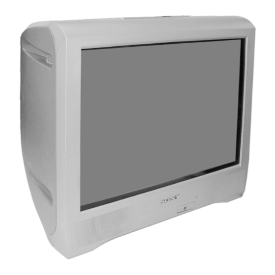
Chapters
Table of Contents
Troubleshooting

Summarization of Contents
REVISION HISTORY
MODEL
List of TV models covered by the revision history.
PART NO.: 9-872-451-01
Part number for the BX1S CHASSIS.
SELF DIAGNOSTIC FUNCTION
SAFETY-RELATED COMPONENT WARNING!!
Critical safety warning for components identified by shading or mark !.
CAUTION
Important safety note regarding short-circuiting the picture tube anode.
1. DIAGNOSTIC TEST INDICATORS
Details on how STANDBY indicator flashes indicate specific problems.
2. DISPLAY OF STANDBY (1) INDICATOR FLASH COUNT
Visual representation of STANDBY indicator flash counts for error diagnosis.
4. SELF-DIAGNOSTIC SCREEN DISPLAY
Procedure to display past failure occurrences on screen for confirmation.
5. HANDLING OF SELF-DIAGNOSTIC SCREEN DISPLAY
Instructions for clearing diagnostic results and re-checking faults after repairs.
6. SELF-DIAGNOSTIC CIRCUIT
Explanation of the self-diagnostic circuit and error triggers.
SECTION 1 DISASSEMBLY
1-1. REAR COVER REMOVAL
Step-by-step guide for removing the rear cover of the TV.
1-3. CHASSIS ASSY REMOVAL
Procedure for removing the main chassis assembly.
1-6. A BOARD REMOVAL
Instructions for removing the 'A' board from the chassis.
1-7. PICTURE TUBE REMOVAL
Detailed steps for removing the picture tube, including anode cap handling.
SECTION 2 SET-UP ADJUSTMENTS
2-1. BEAM LANDING
Procedure for adjusting beam landing using purity control and deflection yoke.
Preparation
Steps to prepare for adjustments, including reducing geomagnetism influence.
2-2. CONVERGENCE
Steps for horizontal and vertical static convergence using magnets and controls.
2-3. FOCUS ADJUSTMENT
Procedure for adjusting focus before white balance alignment.
2-5. WHITE BALANCE ADJUSTMENT
Steps for adjusting white balance in highlight and cutoff conditions.
SECTION 3 CIRCUIT ADJUSTMENTS
3-1. ADJUSTMENTS WITH COMMANDER
Guide to performing service adjustments using the remote commander.
a. ENTERING SERVICE MODE
Sequence to access the service mode on the TV.
c. METHOD OF WRITE INTO MEMORY
Procedure for saving adjusted settings into the TV's memory.
3-3. PICTURE QUALITY ADJUSTMENTS
Adjustments for picture quality like contrast, color, hue, and sharpness.
PMAX/CONTRAST ADJUSTMENT
Procedure for adjusting picture maximum and contrast levels.
SUB COLOR ADJUSTMENT
Adjustment steps for sub color settings, including voltage checks.
3-4. DEFLECTION ADJUSTMENT
Adjustments related to picture deflection and geometry.
H-TRAPEZOID ADJUSTMENT
Procedure for correcting horizontal trapezoid distortion.
3-5. PICTURE DISTORTION ADJUSTMENT
Adjustments for various picture distortions like center, size, and linearity.
H. CENTER ADJUSTMENT (HPOS)
Adjusting horizontal position for optimal vertical centering.
V. ANGLE (HPAR), H. BOW (HBOW), UPPER PIN (UCOP) AND LOW PIN (LCOP) ADJUSTMENTS
Correcting picture geometry issues like angle and bowing.
SECTION 4 DIAGRAMS
4-1. BLOCK DIAGRAM
Overall block diagram of the TV's electronic system.
4-2. CIRCUIT BOARDS LOCATION
Diagram showing the physical location of the main circuit boards (A and C).
4-3. SCHEMATIC DIAGRAM INFORMATION
Conventions used in schematic diagrams, including component notations and references.
4-3-1. C Board Schematic Diagram
Detailed schematic for the C Board (Video Amp).
4-3-2. A Board — Processor (Block 001)
Schematic for the A Board's Processor section (Block 001).
4-3-3. A Board — Audio (Block 002)
Schematic for the A Board's Audio section (Block 002).
4-3-4. A Board — Power Supply (Block 003)
Schematic for the A Board's Power Supply section (Block 003).
4-3-5. A Board — Deflection (Block 004)
Schematic for the A Board's Deflection section (Block 004).
4-3-6. A Board — Tuner (Block 005)
Schematic for the A Board's Tuner section (Block 005).
4-3-7. A Board — Jack (Block 006)
Schematic for the A Board's Jack section (Block 006).
4-3-8. A Board – Heat Sink (Block 007)
List of components mounted on the heat sink for the A Board.
4-4. VOLTAGE MEASUREMENT AND WAVEFORM
Provides voltage measurements and waveforms for IC001 on the A Board.
4-5. PRINTED WIRING BOARDS AND PARTS LOCATION
Layouts of printed wiring boards and component locations for the A Board.
4-6. SEMICONDUCTORS
Reference images and names for diodes, transistors, and ICs.
DIODE
Catalog of diodes used in the TV with their part numbers.
TRANSISTOR
Catalog of transistors used in the TV with their part numbers.
IC
Catalog of integrated circuits used in the TV with their part numbers.
SECTION 5 EXPLODED VIEWS
5-1. CHASSIS
Exploded view of the TV chassis with numbered parts and screw specifications.
Operating Instructions
WARNING
Critical safety warnings regarding high voltages and electrical precautions.
Securing the TV
Instructions for securing the TV to prevent tipping using supplied hardware.
Installation
Steps for initial TV setup and connection.
Getting Started
First-time setup for the remote and TV connection.
Step 1
Instructions for inserting batteries into the remote control.
Step 4
Procedure to set up the TV by following the 'Initial Setup' menu.
Setting up your TV (“Initial Setup”)
Guide to configuring language, channels, and picture position during initial setup.
Overview of Controls
Guide to TV controls and functions.
TV top control, front and rear panels
Identification and function of buttons and terminals on the TV's top, front, and rear panels.
Using the remote control and basic functions
Explanation of remote control buttons and their basic functions.
Advanced Operations
Explanation of advanced TV features and operations.
Viewing Teletext (KV-BT212M81 only)
Instructions for accessing and viewing Teletext information on the TV.
Menu Adjustment
Guide to adjusting TV settings through the menu system.
Introducing the menu system
Overview of the TV's menu system structure and navigation.
Changing the “Picture” setting
Guide to adjusting picture settings like mode, color temperature, and intelligent picture.
Changing the “Sound” setting
Instructions for adjusting sound settings like mode, balance, and surround.
Changing the “Timer” setting
How to set the TV to turn off (Sleep Timer) or turn on (Wake Up Timer) automatically.
Changing the “Channel Setup” setting
Procedures for preset channels, labeling, blocking, and sorting channels.
Changing the “Setup” setting
Instructions for changing language, picture rotation, video labels, and color system.
Additional Information
Supplementary information for TV usage.
Connecting optional components
Diagrams showing how to connect external devices like camcorders, VCRs, and audio systems.
Troubleshooting
Guide to diagnosing and resolving common TV viewing problems.
Specifications
Technical specifications of the TV, including power, dimensions, and features.


Need help?
Do you have a question about the TRINITRON KV-BT212M81 and is the answer not in the manual?
Questions and answers