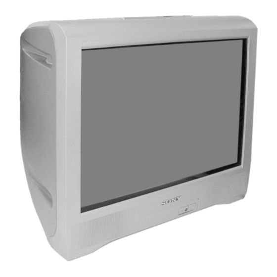
Table of Contents
Advertisement
SERVICE MANUAL
MODEL
COMMANDER DEST.
KV-BT212M40
RM-W101 E
KV-BT212M50
RM-W101 Vietnam SCC-V07P-A
KV-BT212M50
RM-W101 GE
KV-BT212M70
RM-W101 Russia
KV-BT212M80
RM-W101 Saudi Arabia SCC-V10S-A
KV-BT212M80
RM-W101 Russia
KV-BT212M90
RM-W101 Hong Kong SCC-U97L-A
KV-BT212N80
RM-W150 Taiwan
Chassis NO.
MODEL
SCC-U98S-A
SCC-V04M-A
SCC-V13B-A
SCC-V13C-A
SCC-V05K-A
TRINITRON
BX1S
CHASSIS
COMMANDER DEST.
RM-W101 RM-W150
COLOR TV
®
CHASSIS NO.
Advertisement
Table of Contents

Summarization of Contents
Self Diagnostic Function
1. Disassembly
Procedures for disassembling the TV unit, including cover and board removal.
2. Set-up Adjustments
Instructions for initial TV setup adjustments like beam landing and focus.
3. Circuit Adjustments
Procedures for adjusting TV circuits using the remote commander.
4. Diagrams
Technical diagrams including block, schematic, and wiring layouts.
5. Exploded Views
Exploded views illustrating chassis components and assembly.
6. Electrical Parts List
Comprehensive list of electrical components and their part numbers.
Operating Instructions
Guidelines for operating the television unit.
SECTION 1 Disassembly
1-1. Rear Cover Removal
Procedure for removing the rear cover.
1-2. Speaker Removal
Procedure for removing the speaker.
1-3. Chassis Assy Removal
Procedure for removing the chassis assembly.
1-4. Service Position
Describes the service position for the TV.
1-5. Terminal Bracket Removal
Procedure for removing the terminal bracket.
1-6. A Board Removal
Procedure for removing the A board.
SECTION 2 Set-up Adjustments
2-1. Beam Landing
Adjustment procedure for beam landing.
SECTION 3 Circuit Adjustments
3-1. Adjustments With Commander
Adjustments using the remote commander.
3-3. Picture Quality Adjustments
PMAX/CONTRAST ADJUSTMENT
Adjustment for Picture Maximum and Contrast.
SUB HUE ADJUSTMENT
Adjustment for sub-hue.
SUB COLOR ADJUSTMENT
Adjustment for sub-color.
3-4. Deflection Adjustment
H-TRAPEZOID ADJUSTMENT
Adjustment for horizontal trapezoid distortion.
3-5. Picture Distortion Adjustment
H. CENTER ADJUSTMENT (HPOS)
Adjustment for horizontal center.
V. LINEARITY, V. CORRECTION, PIN AMP, AND HORIZONTAL TRAPEZOID ADJUSTMENTS
VERTICAL LINEARITY (VLIN)
Adjustment for vertical linearity.
S CORRECTION (SCOR)
Adjustment for S-correction.
EW PARABOLA/WIDTH (EWPW)
Adjustment for EW parabola/width.
EW TRAPEZIUM (EWTZ)
Adjustment for EW trapezium.
V. ANGLE, H. BOW, UPPER PIN AND LOW PIN ADJUSTMENTS
HORIZONTAL PARALLELOGRAM (HPAR)
Adjustment for horizontal parallelogram.
HORIZONTAL BOW (HBOW)
Adjustment for horizontal bow.
EW UPPER CORNER PARABOLA (UCOP)
Adjustment for EW upper corner parabola.
EW LOWER CORNER PARABOLA (LCOP)
Adjustment for EW lower corner parabola.
SECTION 4 Diagrams
4-1. Block Diagram
Overall block diagram of the TV.
4-4. Voltage Measurement and Waveform
A Board Voltage List and Waveform
Voltage list and waveforms for the A board.
4-5. Printed Wiring Boards and Parts Location
A Board
Printed wiring board layout for the A board.
SECTION 5 Exploded Views
5-1. Chassis
Exploded view of the chassis assembly.
SUPPLEMENT-1
SUBJECT : NEW MODEL ADDITION KV-BT212M80(E)
Information on a new model addition.
SUPPLEMENT-2
SUBJECT : Part Change
Information regarding part changes.


Need help?
Do you have a question about the KV-BT212M70 and is the answer not in the manual?
Questions and answers