Table of Contents
Advertisement
SERVICE MANUAL
Ver 1.0 2002. 03
Revision History
Revision History
M2000 MECHANISM
Link
Link
SPECIFICATIONS
SPECIFICATIONS
SERVICE NOTE
SERVICE NOTE
DISASSEMBLY
DISASSEMBLY
• For INSTRUCTION MANUAL, refer to separate file (992993871.pdf).
• For MECHANISM ADJUSTMENTS, refer to the "8mm Video MECHANICAL ADJUSTMENT MANUAL IX
M2000 MECHANISM " (9-929-861-11).
• The DCR-TRV740E uses two types of 2.5 inch LCD. For identification of the 2.5 inch LCD, see "SECTION 5.
1-5-1. LCD Type Check".
• The DCR-TRV840 uses two types of the type SO or type CA LCD. For identification of the type SO or type CA
LCD, see "SECTION 5. 1-5-1. LCD Type Check".
On the VC-278 board
This service manual provides the information that is premised the circuit board replacement service and not intended repair
inside the VC-278 board.
Therefore, schematic diagram, printed wiring board, waveforms, mounted parts location and electrical parts list of the VC-278
board are not shown.
The following pages are not shown.
Schematic diagram ............................. Pages 4-23 to 4-72
Printed wiring board ............................ Pages 4-87 to 4-90
Waveforms ........................................... Pages 4-93 to 4-95
DCR-TRV738E/TRV740/
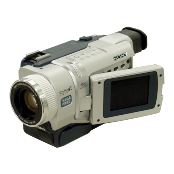
Photo : DCR-TRV740E
BLOCK DIAGRAMS
BLOCK DIAGRAMS
FRAME SCHEMATIC DIAGRAMS
FRAME SCHEMATIC DIAGRAMS
SCHEMATIC DIAGRAMS
SCHEMATIC DIAGRAMS
Mounted parts location ............................. Pages 4-97 to 4-98
Electrical parts list ................................... Pages 6-17 to 6-25
DIGITAL VIDEO CAMERA RECORDER
TRV740E/TRV840
Canadian Model
Australian Model
Hong Kong Model
Chinese Model
East European Model
North European Model
Russian Model
DCR-TRV740/TRV740E/TRV840
Tourist Model
Argentina Model
PRINTED WIRING BOARDS
PRINTED WIRING BOARDS
ADJUSTMENTS
ADJUSTMENTS
REPAIR PARTS LIST
REPAIR PARTS LIST
RMT-814
2
LEVEL
US Model
DCR-TRV740/TRV840
AEP Model
DCR-TRV738E/TRV740E
DCR-TRV740E
E Model
Korea Model
DCR-TRV740
DCR-TRV740/TRV740E
DCR-TRV840
Advertisement
Table of Contents

Summarization of Contents
Specifications
Video Camera Recorder Specifications
Detailed technical specifications for the camcorder's recording system, image device, lens, and general operational parameters.
General and Accessory Specifications
General operational parameters including power requirements, operating temperature, dimensions, mass, battery pack, AC adaptor, and memory stick.
Service Notes and Functions
Service Notes Overview
General service notes, including power supply considerations during repairs and self-diagnosis functions.
Self-Diagnosis Function Details
Explanation of the self-diagnosis display, service mode display, and switching of backup numbers for error codes.
Disassembly Procedures
LCD Unit and Board Disassembly
Step-by-step instructions for disassembling the 2.5-inch and 3.5-inch LCD units and associated boards.
Front Panel, Backlight, and Board Locations
Procedures for disassembling front panel, back light, and diagrams showing circuit and flexible board locations.
Repair Parts List
Exploded Views of Mechanical Sections
Exploded view diagrams showing the physical arrangement and part numbers for various mechanical assemblies.
Electrical Parts List by Board
Detailed list of electrical parts, organized by specific circuit boards like CD-358, LB-076, PD-156, and PD-160.
Schematic Diagrams
Frame Schematic Diagrams
Schematic diagrams showing the overall frame connections of the camcorder's internal components.
Schematic Diagrams - Component Level
Component Schematic Diagrams
Detailed schematic diagrams for individual circuit boards like CD-358, LB-076, SI-032, and control switch blocks.
Printed Wiring Boards
Component Printed Wiring Boards
Printed wiring board layouts for various components, showing component placement and connections.
Adjustments and Service Modes
Camera Section Adjustments
Detailed procedures for adjusting camera parameters, including HALL, Flange Back, and White Balance, with required tools and settings.
Mechanism Section Adjustments
Procedures for adjusting Hi8/Standard8 and Digital8 mechanism settings, including tape path and switching position.
Video Section Adjustments
Procedures for adjusting video section parameters like oscillation, S-Video OUT, and Chroma levels using specific tapes and equipment.
Service Mode Operations
Instructions for using the adjustment remote commander, entering service modes, and processing data for various adjustments.


Need help?
Do you have a question about the TRV740E and is the answer not in the manual?
Questions and answers