Table of Contents
Advertisement
DCR-TRV360 / TRV361 / TRV460 / TRV460E / TRV461E
SERVICE MANUAL
Ver 1.0 2003. 12
Revision History
Revision History
How to use
How to use
Acrobat Reader
Acrobat Reader
M2000/M2200 MECHANISM
Link
Link
SPECIFICATIONS
SPECIFICATIONS
SERVICE NOTE
SERVICE NOTE
DISASSEMBLY
DISASSEMBLY
• For ADJUSTMENTS (SECTION 6), refer to SERVICE MANUAL, ADJ (987629351.pdf).
• For INSTRUCTION MANUAL, refer to SERVICE MANUAL, LEVEL1 (987629341.pdf).
• For MECHANISM ADJUSTMENTS, refer to the "8mm Video MECHANICAL ADJUSTMENT MANUAL IX
M2000 MECHANISM " (9-929-861-11).
• Reference No. search on printed wiring boards is available.
• Table for differences of function of each model.
• TO TAKE OUT A CASSETTE WHEN NOT EJECT (FORCE EJECT)
• HELP: Sheet attachment positions and procedures of processing the flexible boards/harnesses are shown.
On the VC-345 board
This service manual provides the information that is premised the circuit board replacement service and not intended repair
inside the VC-345 board.
Therefore, schematic diagrams, printed wiring boards, mounted parts location and electrical parts list of the VC-345 board are
not shown.
The following pages are not shown.
Schematic diagrams ........................... Pages 4-9 to 4-44
Printed wiring boards .......................... Pages 4-59 to 4-62
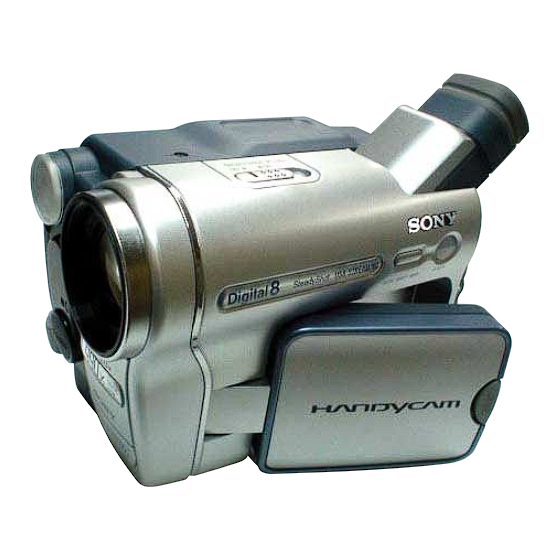
Photo: DCR-TRV460
BLOCK DIAGRAMS
BLOCK DIAGRAMS
FRAME SCHEMATIC DIAGRAMS
FRAME SCHEMATIC DIAGRAMS
SCHEMATIC DIAGRAMS
SCHEMATIC DIAGRAMS
Mounted parts location .................. Pages 4-69 and 4-70
Electrical parts list ......................... Pages 5-16 to 5-24
DIGITAL VIDEO CAMERA RECORDER
RMT-831
LEVEL
US Model
DCR-TRV360/TRV460
Canadian Model
AEP Model
UK Model
East European Model
North European Model
Australian Model
E Model
DCR-TRV361/TRV460/TRV460E/TRV461E
PRINTED WIRING BOARDS
PRINTED WIRING BOARDS
REPAIR PARTS LIST
REPAIR PARTS LIST
2
DCR-TRV460
DCR-TRV460E
Advertisement
Table of Contents

Related Manuals for Sony TRV460E


Summarization of Contents
Service Manual Introduction and Model Overview
Service Manual Structure and Links
Overview of sections, links, and notes within the service manual.
Supported Models and Revision Information
Details on product models covered and manual revision history.
Camcorder Specifications
System and Recording Specifications
Details on video/audio systems, tape formats, and recording times.
Performance and Power Specifications
Covers focus, illumination, input/output, display, power, and operating conditions.
Supplied Accessories
List of items included with the camcorder.
Model Differences and Safety Guidelines
Model Functionality Differences
Table comparing functional differences across various camcorder models.
Safety Warnings and Procedures
Critical safety warnings for components and safety check-out steps.
Unleaded Solder Information
Guidelines for using unleaded solder and its characteristics.
Service Notes and Repair Precautions
Important Repair Handling Notes
Precautions for handling flat cables, connectors, and chip parts.
Power Supply Considerations During Repair
Method to prevent power shut-off when using external power supply.
Force Eject: Cassette Removal Procedure
Step-by-Step Cassette Ejection Guide
Detailed steps to manually remove a cassette when the eject function fails.
Camcorder Self-Diagnosis System
Self-Diagnosis Function Overview
Explanation of how the self-diagnosis function operates and its display modes.
Self-Diagnosis Display Codes
Description of the 4-digit error codes displayed on the viewfinder/LCD.
Self-Diagnosis Code Table and Corrections
Detailed Self-Diagnosis Error Codes
Comprehensive table of self-diagnosis codes, symptoms, and correction steps.
Disassembly Instructions and Flowchart
Overall Disassembly Flow Chart
Visual guide outlining the sequence for disassembling the camcorder.
Component Disassembly Steps
Detailed steps and part references for disassembling specific blocks.
Mechanism Deck and LCD Service Positions
Mechanism Deck Service Position Setup
Instructions for setting the mechanism deck to a service mode for testing.
LCD Service Position Guide
Procedure for accessing the LCD unit for service adjustments.
Circuit Board Locations
Main Circuit Board Placement
Diagrams showing the placement of key circuit boards within the camcorder.
Flexible Board Locations
Flexible Board Routing and Placement
Diagrams illustrating the routing and placement of flexible circuit boards.
Flexible Board and Harness Handling Guide
Harness Attachment Procedures
Guidance on attaching flexible boards and harnesses, including notes.
Block Diagrams Overview and Links
Overall System Block Diagrams
Links to comprehensive diagrams illustrating system functions.
Power Supply Block Diagrams
Links to diagrams detailing power distribution.
Schematic Diagrams Overview and Links
Frame Schematic Diagrams
Overview schematic diagram of the camcorder's main components.
Schematic Diagrams Introduction and References
Schematic Diagram References
Links to schematic diagrams for various boards and blocks.
Schematic Diagram Conventions and Notes
Common Notes and Symbols
Guidelines for understanding schematic symbols, measurement conventions, and general notes.
CD-472 Board Schematic Diagram
CD-472 CCD Imager Schematic
Detailed schematic for the CCD imager circuit.
PD-205 Board Schematic Diagram
PD-205 LCD Driver Schematic
Detailed schematic for the LCD driver and backlight circuit.
SI-041 and FP-792 Schematic Diagrams
SI-041 SteadyShot Schematic
Schematic for the SteadyShot and Jack circuits.
FP-792 Flexible Board Schematic
Schematic for the FP-792 flexible board.
Additional Flexible Board Schematics
FP-228 to FP-802 Flexible Boards Schematics
Schematics for various flexible boards in the FP series.
Control Key Block (CF-5100) Schematic
CF-5100 Control Key Block Diagram
Schematic diagram for the CF-5100 control key block.
Printed Wiring Board (PWB) Overview
Printed Wiring Board References
Links to PWB diagrams for various boards and flexible boards.
Printed Wiring Board Notes and Patterns
PWB Notes and Component Pattern Conventions
Common notes, pattern conventions, and chip part information for PWBs.
CD-472 Board Printed Wiring Board Diagram
CD-472 PWB Component Layout
Diagram showing component placement on the CD-472 board.
PD-205 Board Printed Wiring Board Diagram
PD-205 PWB Component Layout
Diagram showing component placement on the PD-205 board.
SI-041 and FP-792 PWBs Component Layout
SI-041 Board PWB Layout
Component layout for the SI-041 board (Side A and B).
FP-792 Flexible Board PWB Layout
Component layout for the FP-792 flexible board.
Flexible Board PWBs (FP Series)
FP-228 to FP-802 Flexible Board PWBs
Component layout diagrams for FP-228, FP-299, FP-300, FP-301, FP-302, FP-802 boards.
Mounted Parts Location Guide
PD-205 and SI-041 Board Component Locations
Maps showing the physical location of components on specific boards.
Repair Parts List Overview
Exploded Views for Part Identification
Visual guides to identify and locate replacement parts by assembly.
Electrical Parts and Accessories List
Lists of electrical components and optional accessories.
Exploded View: Overall Camcorder Assembly
Overall Assembly Part Numbers
Detailed list of part numbers and descriptions for the overall assembly.
Exploded View: Front Panel Block
Front Panel Components and Part Numbers
List of parts and their corresponding numbers for the front panel assembly.
Exploded View: Lens Block Assembly
Lens Block Components and Part Numbers
List of parts and numbers for the lens assembly, including CCD imager.
Exploded View: LCD Block Assembly
LCD Block Components and Part Numbers
List of parts and numbers for the LCD module and backlight.
Exploded View: Cabinet R Block Assembly
Cabinet R Block Components and Part Numbers
List of parts and numbers for the right cabinet assembly.
Exploded View: EVF Block Assembly
EVF Block Components and Part Numbers
List of parts and numbers for the Electronic Viewfinder (EVF) assembly.
Exploded View: Battery Panel Block Assembly
Battery Panel Block Components and Part Numbers
List of parts and numbers for the battery panel and memory stick connector.
Exploded View: MD Frame Block Assembly
MD Frame Block Components and Part Numbers
List of parts and numbers for the MD frame assembly.
Exploded View: Cassette Compartment and Drum Assembly
Cassette Compartment Parts and Numbers
List of parts and numbers for the cassette compartment and drum.
Exploded View: LS Chassis Block Assembly
LS Chassis Block Parts and Numbers
List of parts and numbers for the LS chassis block assembly.
Exploded View: Mechanical Chassis Block Assembly-1
Mechanical Chassis Block-1 Parts and Numbers
List of parts and numbers for the first mechanical chassis block.
Exploded View: Mechanical Chassis Block Assembly-2
Mechanical Chassis Block-2 Parts and Numbers
List of parts and numbers for the second mechanical chassis block.
Electrical Parts List Details
Component Listings for CD-472, FP Series, and PD-205
Detailed list of electrical components by type for various boards.
Supplied Accessories and Documentation
List of Supplied Accessories
Includes AC adapters, batteries, cables, and manuals provided with the unit.
Instruction Manuals by Region
Regional variations of instruction manuals for different models.
Using Adobe Acrobat Reader for Manual Navigation
Basic Reader Functions: Printing and Finding
Instructions for printing pages and searching for text within the PDF.
Navigation Features: Page and Screen Navigation
Guidance on switching pages, zooming, rotating, and using bookmarks.
Service Manual Revision History
Official Release Information
Details on the initial release version and date of the service manual.
Need help?
Do you have a question about the TRV460E and is the answer not in the manual?
Questions and answers