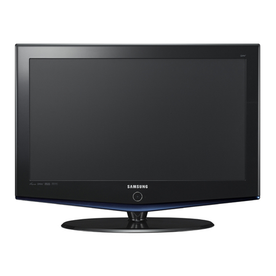
Summarization of Contents
1 Precautions
1-1 Safety Precautions
Covers warnings, servicing, and fire/shock hazards for LCD monitors.
1-2 Servicing Precautions
Details general servicing and electrostatic discharge precautions.
1-3 Static Electricity Precautions
Outlines techniques to reduce component damage from static electricity.
1-4 Installation Precautions
Provides safety guidelines for product installation and ventilation.
14 Reference Information
14-1 Technical Terms
Defines various technical terms related to LCD display technology.
14-2 Connector Configuration
Describes the pin configuration for DVI-D connectors.
14-3 Synchronization Data
Details synchronization parameters for different display modes.
14-4 Panel Specifications
Lists specifications for various LCD panels used in the models.
2 Product Specifications
2-1 Fashion Features
Highlights key features like HD digital tuner, superior picture/sound quality.
2-2 LA26R71B Specifications
Provides detailed specifications for the LA26R71B model.
2-3 LA32R71B Specifications
Provides detailed specifications for the LA32R71B model.
2-4 LA40R71B Specifications
Provides detailed specifications for the LA40R71B model.
2-5 Specifications Comparison
Compares specifications of different models.
2-6 Accessory Specifications
Lists specifications for included accessories.
3 Adjustment and Calibration
3-1 Adjustment Instructions
Provides instructions for color calibration and adjustment procedures.
3-2 How to Enter Maintenance Mode
Explains how to access factory mode and perform panel checks.
3-3 Factory Data
Lists factory settings and options for calibration and tuning.
3-4 White Balance Adjustment
Details white balance adjustments for color accuracy.
3-5 Software Upgrade
Describes the procedure for upgrading firmware.
4 Troubleshooting
4-1 Troubleshooting First Check
Initial checks for troubleshooting, focusing on cable connections and power.
4-2 Troubleshooting by Error Type
Guides troubleshooting based on error symptoms like no picture or no sound.
5 Exploded View and Parts List
5-1 LA26R71B Exploded View
Shows an exploded view of the LA26R71B model with part callouts.
5-2 LA26R71B Parts List
Lists part numbers and descriptions for the LA26R71B model.
5-3 LA32R71B / LA32R71W Exploded View
Exploded view for LA32R71B/LA32R71W models.
5-4 LA32R71B Parts list
Parts list for LA32R71B model.
5-5 LA32R71W Parts list
Parts list for LA32R71W model.
5-6 LA40R71B Exploded View
Exploded view for LA40R71B model.
5-7 LA40R71B Parts list
Parts list for LA40R71B model.
6 Electrical Parts List
6-1 LA26R71B Parts List
Comprehensive list of electrical parts for the LA26R71B model.
6-2 LA32R71B Parts List
Comprehensive list of electrical parts for the LA32R71B model.
6-3 LA40R71B Parts List
Comprehensive list of electrical parts for the LA40R71B model.
6-4 LA32R71W Parts List
Comprehensive list of electrical parts for the LA32R71W model.
7 Block Diagram
7-1 SVP PX Line-up
Shows the signal flow and main components in the SVP PX system.
8 Wiring Diagrams
8-1 LA26R71B / LA32R71B / LA40R71B Wiring Diagram
Illustrates the wiring connections between major components.
8-2 Main Board Layout
Shows the physical layout of the main board and its connectors.
8-3 PIN characteristic
Details the pin assignments and functions for main board connectors.
8-4 Power Board Layout
Depicts the layout of the power board and its connectors.
8-5 CN503-LVDS Signal
Specifies the pin configuration for the CN503-LVDS signal.
8-7 CN801, CNM804 Connectors
Details pin definitions for AC input, main board power supply, and panel control.
8-8 Inverter Power Supply Connectors
Lists pin definitions for inverter power supply connectors.
12 PCB Diagram
12-1 26" Main PCB Diagram
Shows the layout of the main PCB for 26-inch models.
12-2 32", 40" Main PCB Diagram
Shows the layout of the main PCB for 32-inch and 40-inch models.
12-3 26" SMPS board
Image of the SMPS board for 26-inch models.
12-4 32" SMPS board
Image of the SMPS board for 32-inch models.
12-5 40" IP Board
Image of the IP board for 40-inch models.
9 Schematics
9-1 Power Audio Schematic
Provides the schematic diagram for the power and audio sections.
9-2 Interface Schematic
Shows the schematic for various input interfaces like SCART and HDMI.
9-3 Micom Schematic
Presents the schematic diagram for the microcontroller (Micom).
9-4 SVP-PX/PX-Power/LBE Schematic
Details schematics for SVP-PX, Power, and LBE components.
9-5 Application Schematic
Displays application-specific schematic diagrams.


Need help?
Do you have a question about the LA32R71W and is the answer not in the manual?
Questions and answers