Advertisement
AUDIO RECEIVER
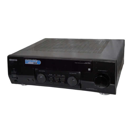
AR-404/KRF-A4030/
QQ
3 7 63 1515 0
A4030E/A4030-S
SERVICE MANUAL
Indicator
(B12-0385-04)
STANDBY
ON/STANDBY
POWER
ON
OFF
PHONES
TE
L 13942296513
Knob *
Phone jack
(K27-)
(E11-0127-05)
Phono jack
(E63-0068-15)
ANTENNA
AM
GND
FM
L
75Ω
R
PHONO
www
Lock terminal board
(E70-0052-05)
.
* Refer to parts list on page 21 .
Knob *
(K29-)
MULTI CONTROL
A SPEAKERS B
Knob *
Knob *
(K29-)
(K29-)
Miniature phone jack
(E11-0293-05)
PLAY IN
PLAY IN
REC OUT
PLAY IN REC OUT PLAY IN
CD
AUX
MD / TAPE1
TAPE2/
MONITOR
x
ao
Phono jack
Phono jack *
y
(E63-0047-15)
(E63-)
i
8
Front glass *
(B10-)
INPUT SELECTOR
BALANCE
PTY
TA/NEWS
DISPLAY
SOUND
SOURCE DIRECT
TAPE 2/MONITOR
BAND
AUTO
MEMORY
Q Q
3
6 7
1 3
Knob *
Knob *
(K29-)
(K29-)
SPEAKERS
R
L
A
+
-
-
+
+
-
-
+
B
R
L
u163
Lock terminal board
(E70-0047-05)
.
2 9
9 4
2 8
© 2000-1/B51-5595-00 (K/K) 3174
Panel *
(A60-)
VOLUME CONTROL
DOWN
1 5
0 5
8
2 9
9 4
Knob *
(K29-)
Power cord bushing
(J42-0083-05)
m
co
AC outlet *
(E03-)
9 9
UP
2 8
9 9
AC power cord *
(E30-)
70%
Advertisement

Related Manuals for Kenwood KRF-A4030-S


Summarization of Contents
Front and Rear Panel Identification
Front Panel Controls and Indicators
Describes controls, indicators, and connectors on the front panel of the audio receiver.
Rear Panel Connections
Identifies and describes the various input and output jacks on the rear panel.
Manual Overview and Safety Information
Included Accessories
Lists all accessories provided with the audio receiver unit.
Microcomputer Reset Procedure
Details the steps to reset the unit's internal microcomputer for troubleshooting.
Circuit Description and Initial Setup
Initial State and Data Backup
Explains the default operational state and how data is backed up.
Tuner and Amplifier Operation
Describes the destination list for tuners and amplifier function settings.
Test Mode Operations
Outlines how to enter, operate, and exit the unit's test mode.
Microprocessor and System Overview
Microprocessor Periphery Block Diagram
Illustrates the main microprocessor's connections to peripheral ICs and components.
Microprocessor Pin Descriptions
X09, IC51 Microprocessor Pin Details
Provides a detailed list and description for each pin of the main microprocessor.
Adjustment Procedures and System Connections
FM Section Adjustments
Covers specific adjustment steps for FM tuning, distortion, and discriminator circuits.
Audio Section Adjustment
Details the procedure for adjusting the audio section's idle current.
Adjustment Setup Connections
Shows the necessary equipment and connections for performing adjustments.
PC Board Layout - Tuner Unit
Tuner Unit Component Placement
Diagram showing the physical location of components on the tuner PC board.
PC Board Layout - Audio Unit
Audio Unit Component Placement
Diagram showing the physical location of components on the audio PC board.
Schematic Diagram - Tuner Unit
Tuner Unit Circuit Details
Complete schematic diagram illustrating the tuner section's circuitry.
Schematic Diagram - FM/AM and System
FM/AM Tuner Circuit Configurations
Circuit diagrams and regional variants for FM and AM tuner sections.
DC Voltage Measurement Points
Identifies specific points for measuring DC voltages during service.
Schematic Diagram - Audio Unit (Part 1)
Audio Input and Control Circuitry
Details the circuits for input selection, sound controls, and muting functions.
Schematic Diagram - Audio Unit (Part 2)
Audio Amplifier and Power Supply Circuits
Illustrates the amplifier stages, power supply, and protection circuit schematics.
Schematic Diagram - Display Unit
Display Unit Circuit Details
Schematic diagram for the front panel display unit's circuitry.
Exploded View of Unit Components
Front Panel and Chassis Assembly
Exploded view showing parts of the front panel, cabinet, and chassis.
Internal Unit Assemblies
Exploded view of the internal circuit boards and modules.
Parts List - General and Accessory Items
Cabinets, Panels, and Front Controls
Lists external parts such as cabinets, panels, knobs, and indicators.
Accessories, Cords, and Manuals
Lists included accessories, power cords, and documentation.
Parts List - Tuner Unit Components
Tuner Unit Capacitors and Resistors
Detailed list of capacitors and resistors used in the tuner unit.
Parts List - Audio Unit Components (Part 1)
Audio Unit Resistors, Diodes, and Zener Diodes
Lists resistors, diodes, and Zener diodes for the audio circuitry.
Parts List - Audio Unit Components (Part 2)
Audio Unit Transistors, ICs, and Modules
Lists semiconductor devices and integrated circuits for the audio section.
Parts List - Connectors, Fuses, and Switches
Connectors, Fuses, Switches, and Coils
Lists various connectors, fuse holders, switches, and inductive components.
Parts List - Semiconductors and Special Components
Transistors, ICs, and Modules
Lists semiconductors and modules including specific ICs and transistors.
Model and Destination Part Variations
Table detailing part differences based on model and region.
Technical Specifications
Audio and Tuner Performance Specs
Details performance metrics for audio and FM/AM tuner sections.
General Unit Specifications
Covers power, dimensions, weight, and operational notes.
Manufacturer and Service Information
Kenwood Global Service Network
Provides contact information for Kenwood service centers worldwide.
Need help?
Do you have a question about the KRF-A4030-S and is the answer not in the manual?
Questions and answers