Table of Contents
Advertisement
Service
Manual
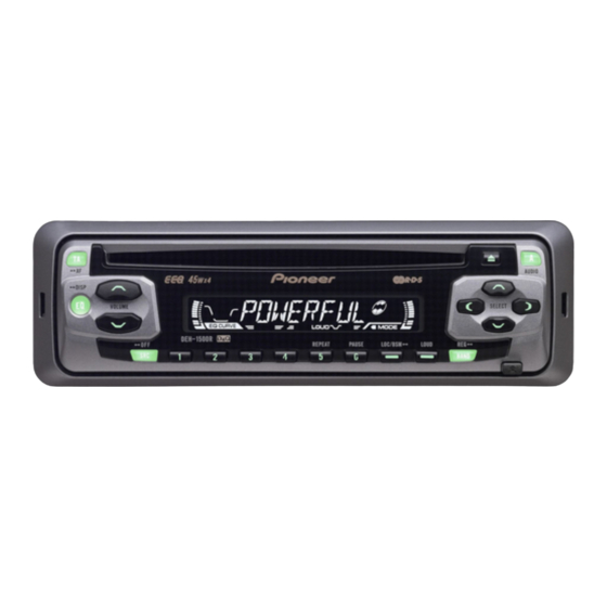
HIGH POWER CD PLAYER WITH FM/AM TUNER
DEH-1550
DEH-1550B
- This service manual should be used together with the following manual(s):
Model No.
Order No.
CX-3026
CRT2944
For details, refer to "Important symbols for good services".
PIONEER CORPORATION
PIONEER ELECTRONICS (USA) INC.
PIONEER EUROPE NV
Haven 1087 Keetberglaan 1, 9120 Melsele, Belgium
PIONEER ELECTRONICS ASIACENTRE PTE.LTD. 253 Alexandra Road, #04-01, Singapore 159936
C PIONEER CORPORATION 2002
XU/ES
Mech. Module Remarks
S10
CD Mech. Module:Circuit Description, Mech.Description, Disassembly
4-1, Meguro 1-Chome, Meguro-ku, Tokyo 153-8654, Japan
P.O.Box 1760, Long Beach, CA 90801-1760 U.S.A.
DEH-1550/XU/ES
XU/ES
ORDER NO.
CRT2970
K-ZZU. NOV. 2002 Printed in Japan
Advertisement
Table of Contents

Related Manuals for Pioneer DEH-1550 ES


Summarization of Contents
Safety Information
Product Safety Precautions
Adhere to product safety regulations and instructions during service operations.
Adjustment Guidelines
Ensure optimal adjustments and spec confirmation for original product performance.
Cleaning Instructions
Clean critical components like optical pickups and heads for performance restoration.
Shipping Mode and Screws
Implement shipping mode or screws to prevent transit damage.
Lubricants, Glues, and Parts
Use specified lubricants, glues, and replacement parts for maintenance.
Exploded Views and Parts Lists
Packing Section Parts List
Lists parts for product packaging and associated manuals.
Exterior Section Parts List
Lists all external components and chassis parts with their numbers.
CD Mechanism Module Parts List
Lists all components and parts specific to the CD mechanism module.
Block and Schematic Diagrams
Block Diagrams
Visual representation of the functional blocks within the Tuner Amp Unit.
Overall Connection Diagrams
Illustrates how major circuit blocks are interconnected throughout the system.
CD Mechanism Module Diagrams
Presents the block diagram specific to the CD mechanism module.
Adjustment Procedures
CD Adjustment Cautions
Provides essential precautions for safely performing adjustments on the CD mechanism.
Grating Check Procedure
Details the process for checking the CD pickup grating angle post-replacement.
Error Mode Diagnostics
Error Mode Indication
Explains how error codes are displayed and their initial meaning.
Error Code List
Comprehensive list of error codes, their descriptions, and probable causes.
General Service Information
Disassembly Procedures
Step-by-step instructions for taking apart various unit components.
Connector Function Descriptions
Details the pin assignments and functions for external connectors.
IC Pin Functions
Lists the pin names, I/O, and functions for key integrated circuits.
Operational Flow Chart
Illustrates the power-on sequence and initial system operations.
Cleaning Procedures
Guidelines for cleaning specific parts, especially before product shipment.
Need help?
Do you have a question about the DEH-1550 ES and is the answer not in the manual?
Questions and answers