Sony DIGITAL HANDYCAM DCR-TR7100E Service Manual
Digital video camera recorder
Hide thumbs
Also See for DIGITAL HANDYCAM DCR-TR7100E:
- Operating instructions manual (120 pages) ,
- Instruction manual (120 pages)
Advertisement
Table of Contents
- 1 Monochrome Electronic Viewfinder System Adjustments
- 2 Repair Parts List
- 3 Service Note
- 4 Power Supply During Repairs
- 5 Service Mode Display
- 6 Mechanism Deck
- 7 Evf Block Assembly
- 8 Lens Block
- 9 Before Starting Adjustment
- 10 Camera Section Adjustment
- 11 Mechanism Section
- 12 Video Section Adjustment
- 13 Service Mode
- 14 Exploded Views
- 15 Electrical Parts List
- Download this manual
DCR-TRV103/TRV110/TRV110E/TRV110P/TRV203/TRV210/
SERVICE MANUAL
Ver 1.0 1999. 02
B800 MECHANISM
NTSC MODEL : DCR-TRV103/TRV110/TRV110P/TRV203/TRV210/
TRV310/TRV310P/TRV315/TR7000
PAL MODEL
: DCR-TRV110E/TRV210E/TRV310E/TR7000E/TR7100E
Video camera
recorder
System
Video recording system
2 rotary heads
Helical scanning system
Audio recording system
Rotary heads, PCM system
Quantization: 12 bits (Fs 32 kHz,
stereo 1, stereo 2), 16 bits
(Fs 48 kHz, stereo)
Video signal
DCR-TRV103/TRV110/TRV110P/
TRV203/TRV210/TRV310/
TRV310P/TRV315/TR7000:
NTSC color, EIA standards
TRV110E/TRV210E/TRV310E/
TR7000E/TR7100E:
PAL color , CCIR standards
Recommended cassette
Hi8 video cassette
Recording/playback time
DCR-TRV103/TRV110/TRV110P/
TRV203/TRV210/TRV310/TRV310P/
TRV315/TR7000: (using 120 min.
cassette)
1 hours
DCR-TRV110E/TRV210E/TRV310E/
TR7000E/TR7100E: (using 90 min.
cassette)
1 hours
Fastforward/rewind time DCR-
TRV103/TRV110/TRV110P/TRV203/
TRV210/TRV310/TRV310P/TRV315/
TR7000: (using 120 min. cassette)
DCR-TRV110E/TRV210E/TRV310E/
TR7000E/TR7100E: (using 90 min.
cassette)
Approx. 8 min.
MICROFILM
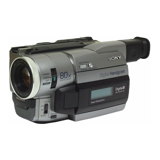
TRV210E/TRV310/TRV310E/TRV310P/TRV315
Photo: DCR-TRV310E
SPECIFICATIONS
Image device
1/4 inch CCD (Charge Coupled
Device)
DCR-TRV103/TRV110/TRV110P/
TRV203/TRV210/TRV310/
TRV310P/TRV315/TR7000:
Approx. 460,000 pixels
(Effective: Approx. 290,000 pixels)
DCR-TRV110E/TRV210E/
TRV310E/TR7000E/TR7100E:
Approx. 800,000 pixels
(Effective: Approx. 400,000 pixels)
Viewfinder
Electronic viewfinder
DCR-TRV315/TR7000/TR7000E/
TR7100E:
Monochrome
DCR-TRV103/TRV110/TRV110E/
TRV110P/TRV203/TRV210/
TRV210E/TRV310/TRV310E/
TRV310P:
Color
Lens
Combined power zoom lens
Filter diameter 1 7/16 in. (37 mm)
20× (Optical),
DCR-TRV103/TRV110/TRV110E:
EE, NE, RU/TRV110P/TRV203/
TRV210/TRV210E: CN/TRV310/
TRV310E/TRV310P: E, HK,
AUS, CN, JE/TRV315/TR7000:
360× (Digital)
DCR-TRV110E: AEP, UK/TRV210E:
AEP, UK/TRV310E: AEP, UK/
TR7000E/TR7100E:
80× (Digital)
DIGITAL VIDEO CAMERA RECORDER
DCR-TR7000/TR7000E/TR7100E
DCR-TRV103/TRV110/TRV210/TRV310/TRV315/TR7000
DCR-TRV103/TRV110/TRV203/TRV210/TRV315/TR7000
DCR-TRV110E/TRV210E/TRV310E/TR7000E
For MECHANISM ADJUSTMENT, refer to
the "8mm Video MECHANICAL
ADJUSTMENT MANUAL
Focal length
5/32 - 2 7/8 in. (3.6 - 72 mm)
When converted to a 35 mm still
camera
1 5/8 - 32 3/8 in. (41 - 820 mm)
Color temperature
Auto
Minimum illumination
DCR-TRV103/TRV110/TRV110P/
TRV203/TRV210/TRV310/
TRV310P/TRV315/TR7000:
1.0 lux (F 1.4)
DCR-TRV110E/TRV210E/
TRV310E/TR7000E/TR7100E:
3 lux (F 1.4)
0 lux (in the NightShot mode)*
* Objects unable to be seen due to
the dark can be shot with
infrared lighting
Input and output
connectors
DCR-TRV103/TRV110/TRV110E: E,
HK, AUS, CN, JE/TRV110P/TRV203/
TRV210/TRV210E: CN/TRV310/
TRV310E: E, HK, AUS, CN, JE/
TRV310P/TRV315/TR7000:
S video input/output
DCR-TRV110E: AEP, UK, EE, NE,
RU/TRV210E: AEP, UK/TRV310E:
AEP, UK/TR7000E/TR7100E:
S video output
4-pin mini DIN
Luminance signal: 1 Vp-p,
75 ohms, unbalanced
RMT-814
US Model
Canadian Model
E Model
DCR-TRV110/TRV110E/TRV110P/
TRV310/TRV310E/TRV310P
Hong Kong Model
DCR-TRV110/TRV110E/TRV310/TRV310E
AEP Model
DCR-TRV110E/TRV210E/TRV310E/
TR7000E/TR7100E
UK Model
Tourist Model
DCR-TRV110E/TRV310/TRV310E
Australian Model
DCR-TRV110E/TRV310E
Brazilian Model
DCR-TRV110
Chinese Model
DCR-TRV110E/TRV210E/TRV310E
East European Model
North European Model
Russian Model
DCR-TRV110E
Taiwan Model
DCR-TRV310
" (9-973-801-11).
DCR-TRV103/TRV110/TRV110P/
TRV203/TRV210/TRV310/
TRV310P/TRV315/TR7000:
Chrominance signal: 0.286 Vp-p,
DCR-TRV110E/TRV210E/
TRV310E/TR7000E/TR7100E:
Chrominance signal: 0.3 Vp-p
75 ohms, unbalanced
DCR-TRV103/TRV110/TRV110E: E,
HK, AUS, CN, JE/TRV110P/TRV203/
TRV210/TRV210E: CN/TRV310/
TRV310E: E, HK, AUS, CN, JE/
TRV310P/TRV315/TR7000:
Video input/output
DCR-TRV110E: AEP, UK, EE, NE,
RU/TRV210E: AEP, UK/TRV310E:
AEP, UK/TR7000E/TR7100E:
Video output
Phono jack, 1 Vp-p, 75 ohms,
unbalanced
DCR-TRV103/TRV110/TRV110E: E,
HK, AUS, CN, JE/TRV110P/TRV203/
TRV210/TRV210E: CN/TRV310/
TRV310E: E, HK, AUS, CN, JE/
TRV310P/TRV315/TR7000:
Audio input/output
DCR-TRV110E: AEP, UK, EE, NE,
RU/TRV210E: AEP, UK/TRV310E:
AEP, UK/TR7000E/TR7100E:
Audio output
Phono jacks (2: stereo L and R)
327 mV, (at output impedance
47 kilohms) impedance less than
2.2 kilohms
RFU DC OUT
Special minijack, DC 5V
Advertisement
Table of Contents

Related Manuals for Sony DIGITAL HANDYCAM DCR-TR7100E


Summarization of Contents
Specifications
Image Device Specifications
Details about the camcorder's image sensor, including pixel count.
Lens Specifications
Details on the camcorder's combined power zoom lens.
Input and Output Connectors
Details on the camcorder's input and output connection types.
SECTION 1 GENERAL
Quick Start Guide
Provides initial steps for setting up and operating the camcorder.
Recording – Basics
Covers fundamental procedures for recording video and audio.
Playback – Basics
Explains the basic steps for playing back recorded video and audio.
Troubleshooting
Offers solutions for common problems encountered with the camcorder.
SECTION 2 DISASSEMBLY
2-1. 2.5 Inch LCD Unit, PD-105 Board
Procedure for disassembling the 2.5-inch LCD unit and PD-105 board.
2-5. Mechanism Deck
Step-by-step guide for disassembling the camcorder's mechanism deck.
2-10. Mechanism Deck, VC-213, DD-117, PJ-95, 96, 98 Boards
Disassembly instructions for key internal boards and mechanism deck.
SECTION 3 BLOCK DIAGRAMS
3-1. Overall Block Diagram (1)
Diagram illustrating the overall system architecture of the camcorder (part 1).
3-3. Power Block Diagram (1)
Diagram showing the camcorder's power supply block and its components (part 1).
SECTION 4 PRINTED WIRING BOARDS AND SCHEMATIC DIAGRAMS
4-1. Frame Schematic Diagram-1
Schematic diagram detailing the camcorder's internal circuitry (frame diagram 1).
VC-213 Board (1/13) Camera Processor
Schematic diagram for the VC-213 board, focusing on the camera processor.
SECTION 5 ADJUSTMENTS
5-1. Camera Section Adjustment
Procedures for adjusting various camera-related functions and parameters.
5-2. Mechanism Section Adjustment
Procedures for adjusting and checking the camcorder's mechanism section.
5-3. Video Section Adjustment
Procedures for adjusting video signal parameters and performance.
5-4. Service Mode
Instructions for accessing and utilizing the camcorder's service mode.
SECTION 6 REPAIR PARTS LIST
6-1. Exploded Views
Visual breakdown of camcorder assemblies with part references.
6-2. Electrical Parts List
Comprehensive list of electrical components used in the camcorder.
Need help?
Do you have a question about the DIGITAL HANDYCAM DCR-TR7100E and is the answer not in the manual?
Questions and answers