Table of Contents
Advertisement
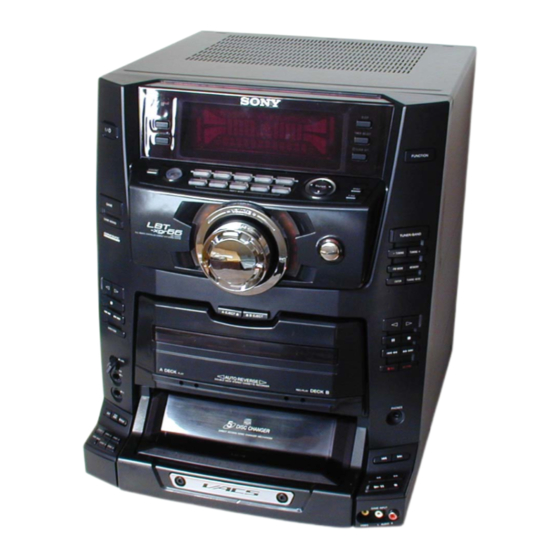
HCD-XGR66/XGR600
SERVICE MANUAL
Ver 1.0 2003.03
• HCD-XGR66/XGR600 are the Amplifier,
CD player, tape deck and tuner in LBT-
XGR66/XGR600.
AUDIO POWER SPECIFICATIONS
(LBT-XGR600 USA model only)
POWER OUTPUT AND TOTAL HARMONIC
DISTORTION:
With 6 ohm loads, both channels driven, from 120 – 10,000 Hz: rated 160
watts per channel minimum RMS power, with no more than 10% total
harmonic distortion from 250 milliwatts to rated output.
Amplifier section
LBT-XGR600
Front speaker
Continuous RMS power output (reference):
175 + 175 watts (6 ohms at 1 kHz, 10% THD)
Total harmonic distortion less than 0.07% (6 ohms at 1 kHz, 80 W)
LBT-XGR66
The following measured at AC 120, 220, 230 – 240 V 50/60 Hz
DIN power output (rated): 220 + 220 watts (6 ohms at 1 kHz, DIN)
Continuous RMS power output (reference):
250 + 250 watts (6 ohms at 1 kHz, 10% THD)
Inputs
PHONO IN (phono jacks):
sensitivity 3 mV, impedance 47 kilohms
MIC (phone jack):
sensitivity 1 mV, impedance 10 kilohms
GAME INPUT AUDIO L/R (phono jacks):
sensitivity 250 mV, impedance 47 kilohms
GAME INPUT VIDEO (phono jack):
1Vp-p, 75 ohms
Sony Corporation
9-877-213-01
Home Audio Company
2003C0200-1
Published by Sony Engineering Corporation
© 2003.03
PHOTO :HCD-XGR66
Model Name Using Similar Mechanism
CD
CD Mechanism Type
Section
Base Unit Name
Optical Pick-up Name
TAPE
Model Name Using Similar Mechanism
Section
Tape Mechanism Type
SPECIFICATIONS
MD (VIDEO) IN L/R (phono jacks):
Outputs
PHONES (stereo phone jack):
MD (VIDEO) OUT L/R (phono jacks):
VIDEO OUT (phono jack):
FRONT SPEAKER:
CD player section
System
Laser
Frequency response
Signal-to-noise ratio
Dynamic range
CD OPTICAL DIGITAL OUT
(square optical connector jack, rear panel)
Wavelength
Output level
COMPONENT Hi-Fi STEREO SYSTEM
US Model
HCD-XGR600
E Model
HCD-XGR66
HCD-XGR6/XGR60
CDM37B-30BD60C
BU-30BD60C
A-MAX.3
NEW
CWM43RR23
sensitivity 450 mV (250 mV),
impedance 47 kilohms
accepts headphones of 8 ohms or more
voltage 250 mV, impedance 1 kilohms
max. output level 1Vp-p,
load impedance 75 ohms
accepts impedance of 6 to 16 ohms
Compact disc digital audio system
Semiconductor laser
(λ=795 nm)
Emission duration: continuous
2 Hz – 20 kHz (±0.5 dB)
More than 90 dB
More than 90 dB
660 nm
–18 dBm
— Continued on next page —
Advertisement
Table of Contents

Related Manuals for Sony XGR600


Summarization of Contents
Section 2 Disassembly Procedures
Disassembly: Case and Back Panel
Procedure for disassembling the case and back panel.
Disassembly: Front Panel Section
Procedure for removing the front panel section.
Disassembly: Tape Mechanism Deck
Procedure for removing the tape mechanism deck.
Disassembly: Panel FL, Game, TC-A, Tuner, TC-B Boards
Procedure for removing multiple control and tuner boards.
Disassembly: Key Board
Procedure for removing the key board.
Disassembly: Headphone, Mic VR, Mic Boards
Procedure for removing headphone, mic VR, and mic boards.
Disassembly: Panel VR Board
Procedure for removing the panel VR board.
Disassembly: Front Input Board
Procedure for removing the front input board.
Disassembly: CD-L, Door SW, CD-R Boards
Procedure for removing CD-L, Door SW, and CD-R boards.
Disassembly: Back Panel, DC Fan, Main Board
Procedure for removing back panel, DC fan, and main board.
Disassembly: CD Mechanism Deck
Procedure for removing the CD mechanism deck.
Disassembly: Base Unit-1
Procedure for disassembling Base Unit-1.
Disassembly: Base Unit-2
Procedure for disassembling Base Unit-2.
Disassembly: BD Board
Procedure for removing the BD board.
Disassembly: Disc Table
Procedure for removing and adjusting the disc table.
Section 3 Test Mode Operations
MC Cold Reset Procedure
Clears all data to initial conditions.
AM Tuning Interval Change-over
Selects AM tuning interval between 9 kHz or 10 kHz.
CD Ship Mode
Moves the optical pick-up to a position durable to vibration.
LED and Key Check Mode
All LEDs and fluorescent indicator tube light up.
Sled Servo Mode (CD Service Mode)
Allows free operation of the CD sled motor.
FUNCTION Name Change-over
Switches external input terminal name between VIDEO or MD.
Aging Mode
Checks tape deck section operation in parallel.
Section 4 Mechanical Adjustments
Mechanical Adjustment Precautions
General precautions before performing mechanical adjustments.
Torque Measurement Specifications
Specifications for torque measurements on various modes.
Section 5 Electrical Adjustments
Electrical Adjustment Precautions
General precautions before performing electrical adjustments.
Test Tape Specifications
Specifications for test tapes used in adjustments.
Record/Playback Head Azimuth Adjustment
Procedure for adjusting head azimuth for decks.
CD Section Adjustment Procedures
Adjustments for CD section including S-Curve and RF Level.
Section 6 Diagrams and Schematics
Circuit Board Location Overview
Diagram showing the location of all circuit boards.
Block Diagrams
Block diagrams for CD servo, tuner/tape, and main sections.
Printed Wiring Board - BD Section
Layout of the BD board.
Schematic Diagram - BD Section
Schematic for the BD board.
Printed Wiring Board - Motor/LED Section
Layout of the motor and LED boards.
Schematic Diagram - Motor/LED Section
Schematic for the motor and LED sections.
Schematic Diagram - Main Section (1/4)
Part 1 of the main section schematic.
Schematic Diagram - Main Section (2/4)
Part 2 of the main section schematic.
Schematic Diagram - Main Section (3/4)
Part 3 of the main section schematic.
Schematic Diagram - Main Section (4/4)
Part 4 of the main section schematic.
Printed Wiring Board - Main Section
Layout of the main board.
Printed Wiring Board - CD-L, CD-R Section
Layout of the CD-L and CD-R boards.
Schematic Diagram - CD-L, CD-R Section
Schematic for the CD-L and CD-R boards.
Printed Wiring Board - TC-A, TC-B Section
Layout of the TC-A and TC-B boards.
Schematic Diagram - TC-A, TC-B Section
Schematic for the TC-A and TC-B boards.
Printed Wiring Board - Panel VR, Key Section
Layout of the panel VR and key boards.
Schematic Diagram - Panel VR, Key Section
Schematic for the panel VR and key boards.
Printed Wiring Board - Panel FL Section
Layout of the panel FL board.
Schematic Diagram - Panel FL Section
Schematic for the panel FL board.
Printed Wiring Board - Power Amp Section
Layout of the power amp board.
Schematic Diagram - Power Amp Section
Schematic for the power amp section.
Schematic Diagram - Mic Section
Schematic for the mic section.
Printed Wiring Board - Power Supply Section
Layout of the power supply board.
Schematic Diagram - Power Supply Section
Schematic for the power supply section.
IC Pin Functions
Pin assignments and functions for key ICs.
IC Block Diagrams
Block diagrams for key integrated circuits.
Section 7 Exploded Views
Exploded View: Case and Back Panel
Exploded view of the case and back panel assembly.
Exploded View: Front Panel Section-1
Exploded view of the front panel components.
Exploded View: Front Panel Section-2
Exploded view of additional front panel components.
Exploded View: Chassis Section
Exploded view of the main chassis assembly.
Exploded View: CD Mechanism Deck
Exploded view of the CD mechanism deck.
Exploded View: Base Unit Section
Exploded view of the base unit assembly.
Section 8 Electrical Parts List
BD Section Parts List
List of electrical parts for the BD board.
Front Input, Game, Headphone, Key Parts List
List of parts for front input, game, headphone, and key boards.
Main Section Parts List
List of electrical parts for the main board.
Panel FL, Panel VR Parts List
List of parts for panel FL and panel VR boards.
Sensor, Sub Trans, TC-A, TC-B Parts List
List of parts for sensor, sub trans, TC-A, and TC-B boards.
Tuner Section Parts List
List of electrical parts for the tuner section.
Need help?
Do you have a question about the XGR600 and is the answer not in the manual?
Questions and answers