Table of Contents

Advertisement

HCD-GX45/RG440
SERVICE MANUAL
Ver 1.0 2003. 07
• HCD-GX45/RG440 is the
tuner, deck, CD and amplifier
section in MHC-GX45/RG440S.
AUDIO POWER SPECIFICATIONS
(HCD-GX45 USA model only)
POWER OUTPUT AND TOTAL HARMONIC
DISTORTION:
With 6 ohm loads, both channels driven, from
120 – 10,000 Hz; rated 120 watts per channel
minimum RMS power, with no more than 10 %
total harmonic distortion from 250 milliwatts to
rated output.
Amplifier section
North American models:
HCD-GX45:
Front speaker
Continuous RMS power output (reference):
120 + 120 watts (6 ohms at
1 kHz, 10% THD)
Total harmonic distortion less than 0.07% (6 ohms at
1 kHz, 60 W)
Sub woofer
Continuous RMS power output (reference):
120 watts (6 ohms at
60 Hz, 10% THD)
Total harmonic distortion less than 0.07% (6 ohms at
60 Hz, 60 W)
European and Russian models:
HCD-RG440:
Front speaker
DIN power output (rated): 80 + 80 watts
(6 ohms at 1 kHz, DIN)
Continuous RMS power output (reference):
100 + 100 watts (6 ohms at
1 kHz, 10% THD)
Music power output (reference):
200 + 200 watts (6 ohms at
1 kHz, 10% THD)
Sony Corporation
9-961-068-01
2003G04-1
Home Audio Company
© 2003. 07
Published by Sony Engineering Corporation
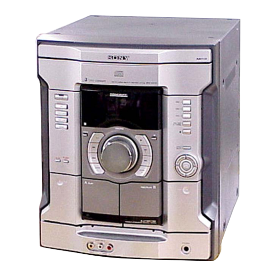
(Photo: HCD-GX45)
Model Name Using Similar Mechanism
CD
CD Mechanism Type
Section
Base Unit Name
Optical Pick-up Name
Tape Deck Model Name Using Similar Machanism
Section
Tape Transport Mechanism Type
SPECIFICATIONS
Sub woofer
DIN power output (rated): 80 watts (6 ohms at
Continuous RMS power output (reference):
Music power output (reference):
Other models:
HCD-RG440:
The following measured at AC 120, 220, 240 V,
50/60 Hz
DIN power output (rated): 80 + 80 watts
Continuous RMS power output (reference):
Inputs
GAME INPUT AUDIO L/R (phono jacks):
GAME INPUT VIDEO (phono jack):
Outputs
PHONES (stereo mini jack):
COMPACT DISC DECK RECEIVER
US Model
Canadian Model
AEP Model
UK Model
Australian Model
HCD-RG440
NEW
CDM74F-K6BD71A
BU-K6BD71A
KSS-213DCP
CX-JT8
CWM43FF-13
60 Hz, DIN)
100 watts (6 ohms at
60 Hz, 10% THD)
200 watts (6 ohms at
60 Hz, 10% THD)
(6 ohms at 1 kHz, DIN)
100 + 100 watts (6 ohms at
1 kHz, 10% THD)
voltage 250 mV,
impedance 47 kilohms
1 Vp-p, 75 ohms
accepts headphones of
8 ohms or more
– Continued on next page –
HCD-GX45
1

Advertisement

Table of Contents
loading

Summary of Contents for Sony HCD-GX45

  • Page 1 US Model Canadian Model Ver 1.0 2003. 07 HCD-GX45 AEP Model UK Model Australian Model HCD-RG440 • HCD-GX45/RG440 is the tuner, deck, CD and amplifier section in MHC-GX45/RG440S. (Photo: HCD-GX45) Model Name Using Similar Mechanism CD Mechanism Type CDM74F-K6BD71A Section...
  • Page 2 REPLACE THESE COMPONENTS WITH SONY PARTS WHOSE NE REMPLACER CES COMPOSANTS QUE PAR DES PIÈCES PART NUMBERS APPEAR AS SHOWN IN THIS MANUAL OR SONY DONT LES NUMÉROS SONT DONNÉS DANS CE MANUEL IN SUPPLEMENTS PUBLISHED BY SONY. OU DANS LES SUPPLÉMENTS PUBLIÉS PAR SONY.
  • Page 3 HCD-GX45/RG440 SAFETY CHECK-OUT CAUTION Use of controls or adjustments or performance of procedures After correcting the original service problem, perform the following other than those specified herein may result in hazardous safety check before releasing the set to the customer: radiation exposure.
  • Page 4: Table Of Contents

    HCD-GX45/RG440 MODEL IDENTIFICATION MODEL PARTS No. GX45: US, CND 4-244-697-31 – BACK PANEL – RG440: AEP, UK, AUS 4-244-697-41 PARTS No. • Abbreviation CND : Canadian model AUS : Australian model TABLE OF CONTENTS 1. GENERAL 5-8. Circuit Boards Location ............ 29 5-9.
  • Page 5: General

    HCD-GX45/RG440 SECTION 1 GENERAL This section is extracted from instruction manual.
  • Page 6: Disassembly

    HCD-GX45/RG440 SECTION 2 DISASSEMBLY Note : Disassemble the unit in the order as shown below. 2-1. CASE (TOP) (Page 7) 2-13. SENSOR BOARD 2-12. CD BLOCK ASSY (Page 14) (Page 13) 2-2. CD DOOR (Page 7) 2-16. BD BOARD 2-14. MOTOR (TB) BOARD...
  • Page 7: Case (Top)

    HCD-GX45/RG440 Note : Follow the disassembly procedure in the numerical order given. 2-1. CASE (TOP) qf case (top) qa two screws (+BVTP 3 × 10) 6 two screws (case 3 TP2) case (side-L) 8 screw (+BVTP 3 × 10) case (side-R)
  • Page 8: Cd Mechanism Block

    HCD-GX45/RG440 2-3. CD MECHANISM BLOCK 8 CD mechanism block 1 CN701 2 three screws (+BVTP 3 × 10) 3 screw (+BVTP 3 × 10) 7 CN312 (flat type) MAIN board 4 screw (+BVTP 3 × 10) MAIN board...
  • Page 9: Front Panel Section

    HCD-GX45/RG440 2-4. FRONT PANEL SECTION TRANS board 1 CN003 4 CN305 3 CN311 (flat type) 8 screw (+BVTP 3 × 8) 2 CN304 5 CN203 (flat type) 6 CN202 7 CN310 0 front panel section 9 three screws (+BVTP 3 × 8 )
  • Page 10: Tape Mechanism Deck

    HCD-GX45/RG440 2-5. TAPE MECHANISM DECK 1 connector 2 six screws (+BVTP 2.6 × 8) 3 tape mechanism deck 2-6. PANEL BOARD, 6 STREAM LED BOARD, REMOTE BOARD 5 three screws (+BVTP 2.6 × 8) qa REMOTE board 6 two screws (+BVTP 2.6 ×...
  • Page 11: Game Jack Board, H/P Jack Board

    HCD-GX45/RG440 2-7. GAME JACK BOARD, H/P JACK BOARD 1 two screws (+BVTP 2.6 × 8) 2 GAME JACK board 3 screw (+BVTP 2.6 × 8) 4 H/P JACK board 2-8. BACK PANEL SECTION 7 back panel section 4 screw (+BVTP 3 × 10) 3 two screws (+BVTP 3 ×...
  • Page 12: Main Board

    HCD-GX45/RG440 2-9. MAIN BOARD MAIN board 2 MAIN board 1 two screws (+BVTP 3 × 10) 2-10. POWER AMP BOARD, SUBWOOFER BOARD 3 screw (+BVTP 3 × 8) two claws 5 screw 4 screw (+BVTP 3 × 10) (+BVTP 3 × 8) 6 screw (+BVTP 3 ×...
  • Page 13: Sw Board, Driver Board

    HCD-GX45/RG440 2-11. SW BOARD, DRIVER BOARD 7 CN702 (flat type) 4 CN703 6 DRIVER board 2 SW board 3 CN704 1 screw 5 two screws (+BTTP (M2.6)) (+BTTP (M2.6)) 2-12. CD BLOCK ASSY 1 floating screw (+PTPWH M2.6) 2 holder (213) assy...
  • Page 14: Sensor Board

    HCD-GX45/RG440 2-13. SENSOR BOARD 1 floating screw (+PTPWH M2.6) 2 tray 8 screw (+BTTP (M2.6)) 3 belt (table) 9 SENSOR board 4 floating screw (+PTPWH M2.6) 5 pulley (table) 6 floating screw (+PTPWH M2.6) 0 CN731 7 gear (geneva) 2-14. MOTOR (TB) BOARD...
  • Page 15: Motor (Ld) Board

    HCD-GX45/RG440 2-15. MOTOR (LD) BOARD 2 two screws (+BTTP (M2.6)) 4 Remove the two solderings of motor. 3 MOTOR (LD) board 5 loading motor assy (M751) 1 belt (loading) 2-16. BD BOARD 5 CN708 (flat type) 4 BD board 1 screw (+BTP 2.6 ×...
  • Page 16: Optical Pick-Up

    HCD-GX45/RG440 2-17. OPTICAL PICK-UP 3 Remove the optical pick-up (KSS-213D) in the direction of the arrow B . 1 gear (A) 2 sled shaft 1 Slide the lever in the direction of arrow A .
  • Page 17: Test Mode

    HCD-GX45/RG440 SECTION 3 TEST MODE [COLD RESET] [CD TRAY LOCK MODE] • The cold reset clears all data including preset data stored in the • This mode is used to unable to take sample disc out of tray in the RAM to initial conditions.
  • Page 18 HCD-GX45/RG440 [AGING MODE] 3. Tape Deck Section The sequence during the aging mode is following as below. • This mode can be used for operation check of CD section and If an error occurred, stop display that step. tape deck section.
  • Page 19 HCD-GX45/RG440 [GC TEST MODE] [MODEL, DESTINATION AND VERSION DISPLAY] • This mode is used to check the fluorescent indicator tube, LED • This mode is used to check the model, destination and software and key. version. Procedure: Procedure: 1. Press the [POWER] key to turn the power ON.
  • Page 20: Electrical Adjustments

    HCD-GX45/RG440 SECTION 4 ELECTRICAL ADJUSTMENTS Note: Clear RF signal waveform means that the shape “ ◊ ” can be CD SECTION clearly distinguished at the center of the waveform. Note: RF signal waveform 1. CD Block is basically designed to operate without adjustment.
  • Page 21: Diagrams

    HCD-GX45/RG440 SECTION 5 DIAGRAMS 5-1. IC PIN DESCRIPTIONS • IC309 BU2099FV (MULTI CONTROLLER) (MAIN BOARD) Pin No. Pin Name Pin Description — Ground pin — Not used. (Open) DATA Serial data input from the tape mechanism controller CLOCK Serial data transfer clock signal input from the system controller Serial data latch pulse clock signal input from the system controller Recording on/off control signal output “L”: recording...
  • Page 22 HCD-GX45/RG440 • IC310 BU2099FV (BASS BOOST CONTROLLER) (MAIN BOARD) Pin No. Pin Name Pin Description — Ground pin — Not used. (Open) DATA Serial data input from the multi controller CLOCK Serial data transfer clock signal input from the system controller...
  • Page 23 HCD-GX45/RG440 • IC601 LC876780B-51Y0-E (SYSTEM CONTROL, FLD CONTROL) (PANEL BOARD) Pin No. Pin Name Pin Description SYS MUTE System mute signal output BU1924 DATA GX45: Not used. (Connected to ground.) RG440: Serial data signal input PWR DOWN Power down signal input...
  • Page 24 HCD-GX45/RG440 Pin No. Pin Name Pin Description TUNER TUNED Tuner tuning signal input from the tuner unit TUNER STEREO Tuner stereo signal input from the tuner unit CD DRF CD DRF signal input CD WRQ CD WRQ signal input CD NUMBER SENSOR...
  • Page 25: Block Diagram -Cd Section

    HCD-GX45/RG440 5-2. BLOCK DIAGRAM — CD SECTION — RF AMP, FOCUS/TRACKING ERROR AMP, DIGITAL SIGNAL PROCESSOR, DIGIRAL SERVO PROCESSOR, • R-ch is omitted due to same as L-ch. DIGITAL FILTER, D/A CONVERTER • SIGNAL PATH IC721 : CD PLAY FIN2...
  • Page 26: Block Diagram -Tuner/Tape/Panel Section

    HCD-GX45/RG440 5-3. BLOCK DIAGRAM — TUNER/TAPE/PANEL SECTION — DECK A/B SELECT SWITCH, REC/PB EQ AMP IC201 AIN (L) L-CH TAI (L) MUTE EQOUT (L) PB-OUT (L) BIN (L) TAPE-L (PB) AMP/POWER SUPPLY (DECK-A) SECTION R-CH R-CH REC- (Page 27) OUT (L)
  • Page 27: Block Diagram -Amp/Power Supply Section

    HCD-GX45/RG440 5-4. BLOCK DIAGRAM — AMP/POWER SUPPLY SECTION — TUNER/TAPE/PANEL VACS/STR SECTION (Page 26) SWITCHING OUTPUT LEVEL FAN MOTOR M731 TUNER/TAPE/PANEL R-CH DETECT R-CH ON/OFF SWITCH (FAN) SECTION Q20, 21 Q371,373 (Page 26) JK002 SWITCHING R-CH VM+10V Q17, 19, 22 –VH...
  • Page 28: Block Diagram -Sub Woofer Section

    HCD-GX45/RG440 5-5. BLOCK DIAGRAM — SUB WOOFER SECTION — SWITCHING Q416 OUTPUT LEVEL DETECT Q417,419 SWITCHING Q424-426 –VH OUTPUT LEVEL DETECT Q422,423 –VL CURRENT BIAS MIRROR Q408,409 Q403,404 SUBWOOFER SUBWOOFER PRE DRIVE CASCADE FINAL DRIVE SW IN JK401 Q401,402 Q405-407...
  • Page 29: Note For Printed Wiring Boards And Schematic Diagrams

    HCD-GX45/RG440 5-6. NOTE FOR PRINTED WIRING BOARDS AND SCHEMATIC DIAGRAMS 5-7. WAVEFORMS Note on Printed Wiring Board: Note on Schematic Diagram: – BD Board – – MAIN Board – – PANEL Board – • X : parts extracted from the component side.
  • Page 30: Printed Wiring Board -Cd Mechanism Section (1/2)

    HCD-GX45/RG440 5-9. PRINTED WIRING BOARD — CD MECHANISM SECTION (1/2) — • Refer to page 29 for Circuit Boards Location. : Uses unleaded solder. BD BOARD (SIDE A) OPTICAL PICK-UP BLOCK BD BOARD (KSS-213DCP) M702 (SPINDLE) (SIDE B) S701 (LIMIT IN) –...
  • Page 31: Schematic Diagram -Cd Mechanism Section (1/2)

    HCD-GX45/RG440 • Refer to page 29 for Waveforms. 5-10. SCHEMATIC DIAGRAM — CD MECHANISM SECTION (1/2) — • Refer to page 49 for IC Block Diagrams. R732 IC803 R731 R721 R722 C753 R834 R707 C709 C746 C742 C708 R729 C744...
  • Page 32: Printed Wiring Boards -Cd Mechanism Section (2/2)

    HCD-GX45/RG440 5-11. PRINTED WIRING BOARDS — CD MECHANISM SECTION (2/2) — • Refer to page 29 for Circuit Boards Location. : Uses unleaded solder. (Page 38) • Semiconductor Location CN751 Ref. No. Location S751 OPEN/CLOSE D701 D711 DETECT IC701 IC712...
  • Page 33: Schematic Diagram -Cd Mechanism Section (2/2)

    HCD-GX45/RG440 5-12. SCHEMATIC DIAGRAM — CD MECHANISM SECTION (2/2) — • Refer to page 50 for IC Block Diagrams. IC701 IC B/D R702 R701 D701 C715 CN704 C751 CN721 M751 IC712 R712 R713 CN705 C752 CN751 S751 D711 R711 R751...
  • Page 34: Schematic Diagram -Main Section (1/4)

    HCD-GX45/RG440 5-13. SCHEMATIC DIAGRAM — MAIN SECTION (1/4) — • Refer to page 50 for IC Block Diagram. CN101 D102 TU901 C101 C310 C103 R101 C106 C107 R102 C309 C102 C312 C311 C365 R380 Q312 R397 Q311 R355 R356 Q310...
  • Page 35: Schematic Diagram -Main Section (2/4)

    HCD-GX45/RG440 • Refer to page 29 for Waveforms. 5-14. SCHEMATIC DIAGRAM — MAIN SECTION (2/4) — • Refer to page 51 for IC Block Diagram. C268 R266 R220 R268 C248 R286 R216 R272 C260 C272 C266 IC B/D R234 R232...
  • Page 36: Schematic Diagram -Main Section (3/4)

    HCD-GX45/RG440 5-15. SCHEMATIC DIAGRAM — MAIN SECTION (3/4) — (Page 34) CN306 (Page 44) CN310 R364 C444 D311 (Page 39) R421 Q304 Q373 CN303 Q371 D371 R371 C378 JR344 R362 R363 (Page 37) R373 D374 R372 R460 R461 M731 JR333...
  • Page 37: Schematic Diagram -Main Section (4/4)

    HCD-GX45/RG440 5-16. SCHEMATIC DIAGRAM — MAIN SECTION (4/4) — (Page 34) (Page 35) C363 R313 R309 R349 C305 R473 R475 C409 C346 C336 R350 R474 C437 R376 CN304 R311 C359 C394 R383 R342 IC304 IC312 IC302 R357 C348 R432 C368...
  • Page 38: Printed Wiring Board -Main Section

    HCD-GX45/RG440 5-17. PRINTED WIRING BOARD — MAIN SECTION — • Refer to page 29 for Circuit Boards Location. : Uses unleaded solder. • Semiconductor Location ANTENNA Ref. No. Location FM 75Ω COAXIAL D101 D102 D203 TUNER UNIT D204 SUPPLIED WITH THE...
  • Page 39: Printed Wiring Boards And Schematic Diagram -Jack Section

    HCD-GX45/RG440 5-18. PRINTED WIRING BOARDS AND SCHEMATIC DIAGRAM — JACK SECTION — • Refer to page 29 for Circuit Boards Location. H/P JACK BOARD GAME JACK BOARD MAIN BOARD VIDEO OUT BOARD CN310 (Page 36) JK004 WRE004 VIDEO JK002 PHONES...
  • Page 40: Printed Wiring Boards -Panel Section

    HCD-GX45/RG440 5-19. PRINTED WIRING BOARDS — PANEL SECTION — • Refer to page 29 for Circuit Boards Location. : Uses unleaded solder. REMOTE BOARD PANEL BOARD (Page 38) C602 MAIN BOARD CN311 C601 RM601 1-688-083- (12) FLD601(FLUORESCENT INDICATOR TUBE) C639...
  • Page 41: Schematic Diagram -Panel Section

    HCD-GX45/RG440 5-20. SCHEMATIC DIAGRAM — PANEL SECTION — • Refer to page 29 for Waveforms. (Page 36) MAIN BOARD CN311 PANEL BOARD LED607 – 609, 612 HL-30105Q2AT TUNER TAPE A/B GAME /BAND Q602 – 604,0607 LED DRIVE 41 40 39 38 37 36 35 34 D606–610,612,613...
  • Page 42: Printed Wiring Board -Sub Woofer Section

    HCD-GX45/RG440 5-21. PRINTED WIRING BOARD — SUB WOOFER SECTION — • Refer to page 29 for Circuit Boards Location. : Uses unleaded solder. POWER AMP BOARD CN503 (Page 46) CLP1 SUBWOOFER BOARD C428 JW427 JW428 JW426 JW414 JW424 JW423 R433...
  • Page 43: Schematic Diagram -Sub Woofer Section

    HCD-GX45/RG440 5-22. SCHEMATIC DIAGRAM — SUB WOOFER SECTION — R405 R407 D404 D403 D401 R406 R414 Q410 R424 R410 Q401 R408 R430 Q402 R420 C411 R425 C402 Q409 Q412 R401 R402 R419 Q408 R426 C407 R413 R428 R404 C410 C401...
  • Page 44: Schematic Diagram -Power Amp Section (1/2)

    HCD-GX45/RG440 5-23. SCHEMATIC DIAGRAM — POWER AMP SECTION (1/2) — TH501 R529 CN501 R543 R541 R537 D503 Q501 C521 C517 JR513 R521 D501 R559 R539 Q507 Q519 R505 R545 Q509 Q517 R523 C503 C501 R507 R513 R549 (Page 36) Q525...
  • Page 45: Schematic Diagram -Power Amp Section (2/2)

    HCD-GX45/RG440 5-24. SCHEMATIC DIAGRAM — POWER AMP SECTION (2/2) — (Page 44) Q530 R589 R594 R577 Q534 Q535 R100 JW501 R580 D513 Q529 R105 R103 R106 R104 R563 R564 R567 R568 R575 Q536 D515 D511 C531 C529 R578 R574 R576...
  • Page 46: Printed Wiring Board -Power Amp Section

    HCD-GX45/RG440 5-25. PRINTED WIRING BOARD — POWER AMP SECTION — • Refer to page 29 for Circuit Boards Location. : Uses unleaded solder. • Semiconductor Location Ref. No. Location Ref. No. Location H-10 F-10 F-10 G-10 F-10 G-12 G-12 Q501...
  • Page 47: Printed Wiring Board -Transformer Section

    HCD-GX45/RG440 5-26. PRINTED WIRING BOARD — TRANSFORMER SECTION — • Refer to page 29 for Circuit Boards Location. : Uses unleaded solder. (Page 46) • Semiconductor Location Ref. No. Location D902 C-10 D903 C-10 D904 C-10 D905 C-10 D906...
  • Page 48: Schematic Diagram -Transformer Section

    HCD-GX45/RG440 5-27. SCHEMATIC DIAGRAM — TRANSFORMER SECTION — T901 F902 F905 CN902 F903 NOT REPLACEABLE BUILT IN TRANSFORMER F904 F906 RY902 (Page 45) JW902 D906 (US,CND) C901 R901 T902 D903 D902 CN901 D905 D904 JW901 JW909 C902...
  • Page 49: Ic Block Diagrams

    HCD-GX45/RG440 5-28. IC BLOCK DIAGRAMS IC721 LC78646E-E (BD Board) 78 77 76 75 74 73 72 71 69 68 67 66 65 64 63 62 61 FIN1 – FIN2 – TIN1 TBAL – – TIN2 – – TBAL – RFMON...
  • Page 50 HCD-GX45/RG440 IC701, 712 BA6956AN (DRIVER Board) CONTROL LOGIC IC301 M61529FP (MAIN Board) 42 41 39 38 37 34 33 32 31 30 TONE CONTROL ELECTRICAL (BASS/MID/TREBLE) VOLUME INPUT BASS BOOST TONE ATT SURROUND VOCAL INTERFACE DPL BUFFER TONE ATT BASS...
  • Page 51 HCD-GX45/RG440 IC201 HA12237F (MAIN Board) 93/120 PB-NF1 (L) (HIGH/NORM) MUTE 20 TEST MODE 19 IREF AIN (L) 18 GND BIN (L) 17 ALC DET RETURN SW 16 VCC REC-RETURN 15 REC MUTE OFF/ON RETURN SW 14 MUTE ON/OFF BIN (R)
  • Page 52: Exploded Views

    HCD-GX45/RG440 SECTION 6 EXPLODED VIEWS NOTE: • The mechanical parts with no reference • -XX and -X mean standardized parts, so The components identified by mark 0 or dotted line with mark number in the exploded views are not supplied.
  • Page 53: Front Panel Section (1)

    HCD-GX45/RG440 6-2. FRONT PANEL SECTION (1) not supplied (REMOTE board) FLD601 not supplied supplied supplied supplied not supplied (GAME JACK board) not supplied (H/P JACK board) Ref. No. Part No. Description Remark Ref. No. Part No. Description Remark 4-244-686-01 VOLUME KNOB...
  • Page 54: Front Panel Section (2)

    HCD-GX45/RG440 6-3. FRONT PANEL SECTION (2) Ref. No. Part No. Description Remark Ref. No. Part No. Description Remark 4-244-701-01 CASS DOOR SPRING (B) 4-244-661-01 SUB PANEL 4-238-631-01 TAPE SPRING 4-244-669-01 DISPLAY WINDOW 4-244-666-01 CASS (DOOR) (R) 4-231-824-01 CAM (A), HEART...
  • Page 55: Front Panel Section (3)

    4-244-684-01 EQ BUTTON 4-225-252-01 CUSHION (FOOT) 4-244-906-01 CONTROL BUTTON (B) 4-244-680-01 GAME MIXING BUTTON 4-246-087-01 PAUSE BUTTON (A) 4-244-676-01 FUNCTION BUTTON 4-244-679-01 DISC BUTTON 4-244-677-01 POWER LENS 4-244-687-01 GAME MIXING HOLDER 4-244-678-01 FUNCTION LENS 3-038-018-01 EMBLEM, SONY 4-244-683-01 RECORD BUTTON (A)
  • Page 56: Main Board Section

    HCD-GX45/RG440 6-5. MAIN BOARD SECTION not supplied not supplied not supplied not supplied not supplied not supplied F902 F905 T901 F903 F904 F906 not supplied The components identified by Les composants identifiés par une mark 0 or dotted line with mark marque 0 sont critiques pour 0 are critical for safety.
  • Page 57: Cd Mechanism Deck Section (1)

    HCD-GX45/RG440 6-6. CD MECHANISM DECK SECTION (1) (CDM74F-K6BD71A) M741 chassis assy Ref. No. Part No. Description Remark Ref. No. Part No. Description Remark 4-218-253-21 SCREW (M2.6), +BTTP 4-243-820-01 GEAR (TABLE) 1-776-182-11 WIRE (FLAT TYPE) (5 CORE) 4-243-819-01 GEAR (GENEVA) 1-687-134-11 MOTOR (TB) BOARD...
  • Page 58: Cd Mechanism Deck Section (2)

    HCD-GX45/RG440 6-7. CD MECHANISM DECK SECTION (2) (CDM74F-K6BD71A) RE701 BU-K6BD71A M751 Ref. No. Part No. Description Remark Ref. No. Part No. Description Remark 1-687-135-11 DRIVER BOARD 4-243-822-01 LEVER (LIFTER) 4-218-253-31 SCREW (M2.6), +BTTP 1-471-035-11 MAGNET ASSY 1-687-669-11 SW BOARD 4-231-189-01 PULLEY (B), CHUCKING...
  • Page 59: Base Unit Section

    HCD-GX45/RG440 6-8. BASE UNIT SECTION (BU-K6BD71B) The components identified by Les composants identifiés par une mark 0 or dotted line with mark marque 0 sont critiques pour 0 are critical for safety. la sécurité. Replace only with part number Ne les remplacer que par une piéce specified.
  • Page 60: Electrical Parts List

    HCD-GX45/RG440 SECTION 7 ELECTRICAL PARTS LIST NOTE: • Due to standardization, replacements in • Items marked “*” are not stocked since The components identified by mark 0 or dotted line with mark the parts list may be different from the they are seldom required for routine service.
  • Page 61 HCD-GX45/RG440 DRIVER Ref. No. Part No. Description Remark Ref. No. Part No. Description Remark FB808 1-550-907-21 BEAD, FERRITE (CHIP) R817 1-216-827-11 METAL CHIP 3.3K 1/10W R818 1-216-811-11 METAL CHIP 1/10W < IC > R819 1-216-821-11 METAL CHIP 1/10W R820 1-216-821-11 METAL CHIP...
  • Page 62 HCD-GX45/RG440 DRIVER GAME JACK H/P JACK MAIN Ref. No. Part No. Description Remark Ref. No. Part No. Description Remark R713 1-249-433-11 CARBON 1/4W C201 1-162-964-11 CERAMIC CHIP 0.001uF R721 1-249-425-11 CARBON 4.7K 1/4W C202 1-162-964-11 CERAMIC CHIP 0.001uF R722 1-249-425-11 CARBON 4.7K...
  • Page 63 HCD-GX45/RG440 MAIN Ref. No. Part No. Description Remark Ref. No. Part No. Description Remark C310 1-126-964-11 ELECT 10uF C389 1-126-933-11 ELECT 100uF C311 1-126-964-11 ELECT 10uF C390 1-162-953-11 CERAMIC CHIP 100PF C312 1-126-964-11 ELECT 10uF C391 1-162-953-11 CERAMIC CHIP 100PF...
  • Page 64 HCD-GX45/RG440 MAIN Ref. No. Part No. Description Remark Ref. No. Part No. Description Remark C451 1-162-960-11 CERAMIC CHIP 220PF < EARTH TERMINAL > (RG440:AEP,UK) C452 1-162-960-11 CERAMIC CHIP 220PF * G1 1-537-738-21 TERMINAL, EARTH (RG440:AEP,UK) * G2 1-537-738-21 TERMINAL, EARTH (RG440:AEP,UK)
  • Page 65 HCD-GX45/RG440 MAIN Ref. No. Part No. Description Remark Ref. No. Part No. Description Remark Q321 8-729-120-28 TRANSISTOR 2SC1623-L5L6 R284 1-216-833-11 METAL CHIP 1/10W Q322 8-729-120-28 TRANSISTOR 2SC1623-L5L6 R285 1-216-833-11 METAL CHIP 1/10W Q324 8-729-120-28 TRANSISTOR 2SC1623-L5L6 R286 1-216-833-11 METAL CHIP...
  • Page 66 HCD-GX45/RG440 MAIN MOTOR (LD) MOTOR (TB) PANEL Ref. No. Part No. Description Remark Ref. No. Part No. Description Remark R376 1-216-833-11 METAL CHIP 1/10W R480 1-216-833-11 METAL CHIP 1/10W R377 1-216-829-11 METAL CHIP 4.7K 1/10W R481 1-216-829-11 METAL CHIP 4.7K...
  • Page 67 HCD-GX45/RG440 PANEL Ref. No. Part No. Description Remark Ref. No. Part No. Description Remark < CONNECTOR > JR613 1-216-864-11 METAL CHIP 1/10W JR614 1-216-864-11 METAL CHIP 1/10W CN601 1-784-753-11 CONNECTOR, FFC 31P JR615 1-216-864-11 METAL CHIP 1/10W CN602 1-784-731-11 CONNECTOR, FFC 9P...
  • Page 68 HCD-GX45/RG440 PANEL Ref. No. Part No. Description Remark Ref. No. Part No. Description Remark R061 1-216-841-11 METAL CHIP 1/10W R634 1-216-833-11 METAL CHIP 1/10W R062 1-216-841-11 METAL CHIP 1/10W R635 1-216-198-11 RES-CHIP 1/8W R063 1-216-841-11 METAL CHIP 1/10W R638 1-216-835-11 METAL CHIP...
  • Page 69 HCD-GX45/RG440 PANEL POWER AMP Ref. No. Part No. Description Remark Ref. No. Part No. Description Remark R699 1-216-821-11 METAL CHIP 1/10W S619 1-762-875-21 SWITCH, KEYBOARD (DISC 3) R902 1-216-841-11 METAL CHIP 1/10W S620 1-762-875-21 SWITCH, KEYBOARD (DISC SKIP/EX-CHANGE) R903 1-216-829-11 METAL CHIP 4.7K...
  • Page 70 HCD-GX45/RG440 POWER AMP Ref. No. Part No. Description Remark Ref. No. Part No. Description Remark C502 1-163-021-11 CERAMIC CHIP 0.01uF 8-719-988-61 DIODE 1SS355TE-17 C503 1-164-156-11 CERAMIC CHIP 0.1uF 8-719-988-61 DIODE 1SS355TE-17 C504 1-164-156-11 CERAMIC CHIP 0.1uF 8-719-083-67 DIODE UDZS-TE17-20B C505...
  • Page 71 HCD-GX45/RG440 POWER AMP Ref. No. Part No. Description Remark Ref. No. Part No. Description Remark < TRANSISTOR > 1-216-830-11 METAL CHIP 5.6K 1/10W 1-216-206-00 RES-CHIP 2.2K 1/8W 6-550-289-01 TRANSISTOR 2SA1235F 1-216-830-11 METAL CHIP 5.6K 1/10W 8-729-120-28 TRANSISTOR 2SC1623-L5L6 1-216-821-11 METAL CHIP...
  • Page 72 HCD-GX45/RG440 POWER AMP Ref. No. Part No. Description Remark Ref. No. Part No. Description Remark 1-216-827-11 METAL CHIP 3.3K 1/10W R529 1-216-829-11 METAL CHIP 4.7K 1/10W 1-216-827-11 METAL CHIP 3.3K 1/10W R530 1-216-829-11 METAL CHIP 4.7K 1/10W 1-216-234-00 RES-CHIP 1/8W...
  • Page 73 HCD-GX45/RG440 POWER AMP REMOTE SENSOR SUBWOOFER Ref. No. Part No. Description Remark Ref. No. Part No. Description Remark R601 1-216-156-00 RES-CHIP 1/8W C425 1-128-552-51 ELECT 47uF R602 1-216-156-00 RES-CHIP 1/8W (GX45/RG440:AUS) R603 1-216-156-00 RES-CHIP 1/8W C428 1-126-963-11 ELECT 4.7uF R604...
  • Page 74 HCD-GX45/RG440 SUBWOOFER Ref. No. Part No. Description Remark Ref. No. Part No. Description Remark < TRANSISTOR > R434 1-216-833-11 METAL CHIP 1/10W R435 1-216-825-11 METAL CHIP 2.2K 1/10W Q401 6-550-316-01 TRANSISTOR 2SB792A(RS) R436 1-216-825-11 METAL CHIP 2.2K 1/10W Q402 6-550-316-01 TRANSISTOR 2SB792A(RS)
  • Page 75 HCD-GX45/RG440 SUBWOOFER TRANS VIDEO OUT 6 STREAM LED Ref. No. Part No. Description Remark Ref. No. Part No. Description Remark < RELAY > 1-688-081-21 6 STREAM LED BOARD ******************* RY401 1-755-373-11 RELAY < JUMPER RESISTOR > < THERMISTOR > JR002...
  • Page 76 HCD-GX45/RG440 Ref. No. Part No. Description Remark MISCELLANEOUS *************** 1-769-939-11 WIRE (FLAT TYPE) (11 CORE) (GX45) 1-773-003-11 WIRE (FLAT TYPE) (15 CORE) (RG440) 1-796-485-51 DECK, MECHANICAL 1-769-914-11 WIRE (FLAT TYPE) (9 CORE) 1-773-322-11 WIRE (FLAT TYPE) (31 CORE) 1-827-145-11 WIRE (FLAT TYPE) (13 CORE)
  • Page 77 HCD-GX45/RG440 MEMO...
  • Page 78 HCD-GX45/RG440 REVISION HISTORY Clicking the version allows you to jump to the revised page. Also, clicking the version at the upper on the revised page allows you to jump to the next revised page. Ver. Date Description of Revision 2003. 07...

This manual is also suitable for:

Hcd-rg440

Table of Contents