Table of Contents
Advertisement
Quick Links
SERVICE MANUAL
Ver. 1.3 2005.11
HCD-DX150/DX170/DX250 are the amplifier, DVD/
CD and tuner section in DAV-DX150/DX170/DX250.
This system incorporates with Dolby* Digital and Dolby
Pro Logic (II) adaptive matrix surround decoder and the
DTS** Digital Surround System.
* Manufactured under license from Dolby Laboratories.
"Dolby", "Pro Logic" and the double-D symbol are
trademarks of Dolby Laboratories.
** Manufactured under license from Digital Theater
Systems, Inc. "DTS" and "DTS Digital Surround" are
trademarks of Digital Theater Systems, Inc.
AUDIO POWER SPECIFICATIONS
for the US model
POWER OUTPUT AND
TOTAL HARMONIC
DISTORTION:
With 3 ohm loads, both
channels driven, from
200 – 20,000 Hz; rated
55 watts per channel
minimum RMS power,
with no more than 0.7 %
total harmonic distortion
from 250 milli watts to
rated output.
Amplifier section
DX150
North American model:
Surround mode (reference) music power output
Front: 133 W + 133 W
(with SS-TS31)
Center*: 133 W
(with SS-CT31)
Surround*: 133 W + 133
W
(with SS-TS31B)
Subwoofer*: 135 W
(with SS-WS31)
Sony Corporation
9-879-398-04
Home Audio Division
2005K16-1
Published by Sony Engineering Corporation
© 2005.11
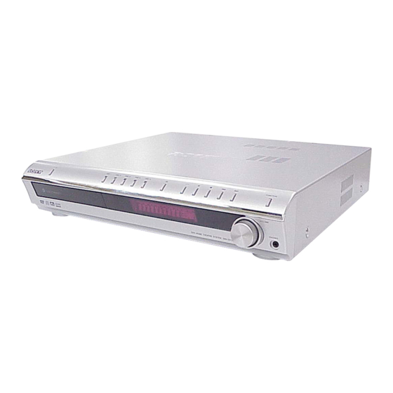
Photo: HCD-DX150
Model Name Using Similar Mechanism
Mechanism Type
Optical Pick-up Name
SPECIFICATIONS
Central/South American models
Stereo mode (rated)
55 W + 55 W (DIN)
Surround mode (reference) music power output
Front: 120 W + 120 W
Center*: 120 W
Surround*: 120 W + 120
W
Subwoofer*: 120 W
Other models:
Stereo mode (rated)
55 W + 55 W (3 ohms at 1
kHz, DIN)
Surround mode (reference) music power output
Front: 133 W + 133 W
(with SS-TS31)
Center*: 133 W
(with SS-CT31)
Surround*: 133 W + 133
W
(with SS-TS31B)
Subwoofer*: 135 W
(with SS-WS31)
DX170
Surround mode (reference) music power output
Front: 143 W + 143 W
(with SS-TS31)
Center*: 143 W
(with SS-CT31)
Surround*: 143 W + 143
W
(with SS-TS31B)
Subwoofer*: 285 W
(with SS-WS32)
HCD-DX150/DX170/
Canadian Model
HCD-DX150/DX170/DX250
Australian Model
DX250
Surround mode (reference) music power output
Depending on the sound field settings and the source,
there may be no sound output.
Inputs
VIDEO/SAT (AUDIO IN) Sensitivity: 250/450 mV
Phones
DVD RECEIVER
DX250
US Model
E Model
HCD-DX150
NEW
CDM81C-DVBU101
KHM-310CAB/C2NP
Front: 143 W + 143 W
(with SS-TS41)
Center*: 143 W
(with SS-CT31)
Surround*: 143 W + 143
W
(with SS-TS31B)
Subwoofer*: 285 W
(with SS-WS32)
Impedance: 50 kilohms
Accepts low-and high-
impedance headphones.
— Continued on next page —
Advertisement
Table of Contents

Summarization of Contents
SPECIFICATIONS
AUDIO POWER SPECIFICATIONS for the US model
Details power output and total harmonic distortion for the US model.
Amplifier section
Lists power output specifications for DX150, DX170, and DX250 models.
Inputs
Specifies sensitivity and impedance for audio inputs and headphones.
MODEL IDENTIFICATION
Rear Panel
Shows model identification labels and their locations on the rear panel.
CAUTION
UNLEADED SOLDER
Explains characteristics and handling of unleaded solder.
SAFETY CHECK-OUT
LEAKAGE TEST
Details methods and limits for AC leakage testing.
SERVICING NOTE
NOTES ON HANDLING THE OPTICAL PICK-UP BLOCK OR BASE UNIT
Warns about electrostatic discharge and handling the flexible board.
Self-diagnosis Function
Explains how to interpret service numbers displayed by the self-diagnosis function.
DISASSEMBLY
3-1. DISASSEMBLY FLOW
Outlines the step-by-step procedure for disassembling the unit.
TEST MODE
1. Cold Reset
Procedure to reset all data and settings to their initial conditions.
2. Panel Test Mode
Checks software version, LCD, LED, and keyboard functionality.
4. DVD Ship Mode
Procedure for returning the set to the customer after repair.
DIAGRAMS
5-1. Block Diagram
Presents block diagrams for RF/SERVO, VIDEO, AMP, AUDIO, and POWER sections.
ELECTRICAL ADJUSTMENT
DVD SECTION
Outlines adjustments and measurements after replacing the base unit.
[RF Level Check]
Connects oscilloscope to check RF signal waveform and level.
DIAGRAMS
THIS NOTE IS COMMON FOR PRINTED WIRING BOARDS AND SCHEMATIC DIAGRAMS.
General notes and symbols used in diagrams.
Circuit Boards Location
Indicates the location of various circuit boards within the unit.
PRINTED WIRING BOARD - DVD MECHANISM SECTION
Component Locations
Shows the physical placement of components on the DVD mechanism board.
SCHEMATIC DIAGRAM - DMB10 SECTION (2/4)
IC Pin Function Description
Details pin functions for IC102 and IC107 on the DMB10 board.
Waveforms
Displays waveforms for IC102 and IC107 on the DMB10 board.
PRINTED WIRING BOARD - MAIN SECTION (SIDE A)
Semiconductor Location
Lists semiconductor components and their positions on the Main board (Side A).
EXPLODED VIEWS
7-1. OVERALL SECTION
Exploded view of the entire unit showing major assemblies.
SUPPLEMENT-1
Board changed to DMB11 board from DMB10 board
Notes board change from DMB10 to DMB11, refers to original manual.
REVISION HISTORY
Revision Details
Lists version history, dates, and descriptions of revisions.


Need help?
Do you have a question about the HCD-DX250 and is the answer not in the manual?
Questions and answers